Display mount with post-installation adjustment features

a technology of display mounting and adjustment features, which is applied in the direction of machine supports, electric apparatus casings/cabinets/drawers, instruments, etc., can solve the problems of affecting the aesthetics of display installation, affecting the appearance of display installation, and strict attention to be paid

Active Publication Date: 2011-02-24
LEGRAND AV INC
View PDF17 Cites 34 Cited by
  • Summary
  • Abstract
  • Description
  • Claims
  • Application Information

AI Technical Summary

Benefits of technology

[0015]In other embodiments, a mount according to the invention may include a shelf assembly operably coupled with one or more of the cross supports, or a speaker attachment operably coupled with one or more of the cross supports.

Problems solved by technology

A typical drawback of these previous mounting devices, however, is that strict attention must be paid during installation of the mounting device to ensure that the display will be mounted in the optimal position on the structure and that the display will be level or aligned with the structure.
Even a very small error in positioning of the mounting device during installation can result in a highly noticeable misalignment of the display when mounted, thereby detracting significantly from the aesthetics of the display installation.
Due to the location of structural elements such as wall framing members, it is often difficult to position a display mount in precisely the position desired on a wall surface.
Further, fasteners used to fasten the mounting device to the wall typically lack precision and may shift during the installation process, leading to misalignment of the mounting device.

Method used


Image

  • Display mount with post-installation adjustment features
  • Display mount with post-installation adjustment features
  • Display mount with post-installation adjustment features

Examples


Embodiment Construction

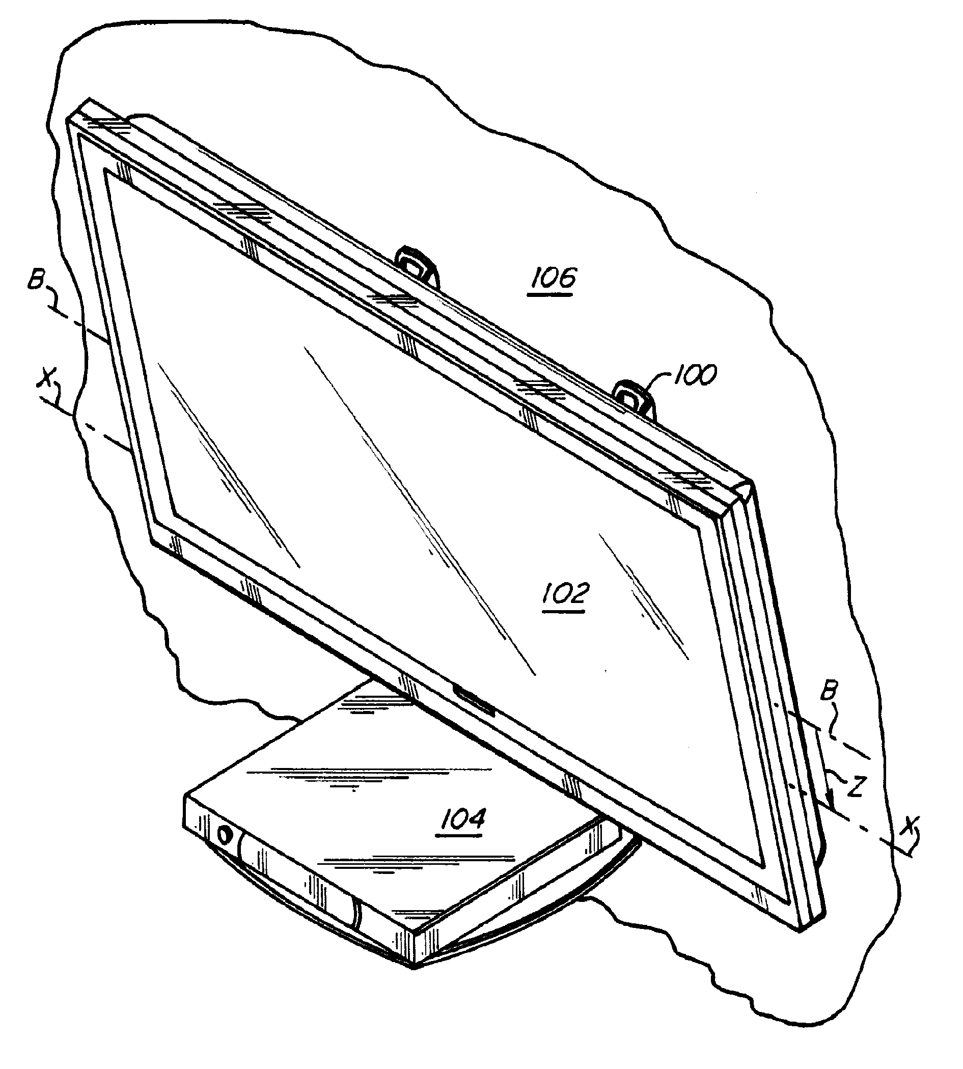
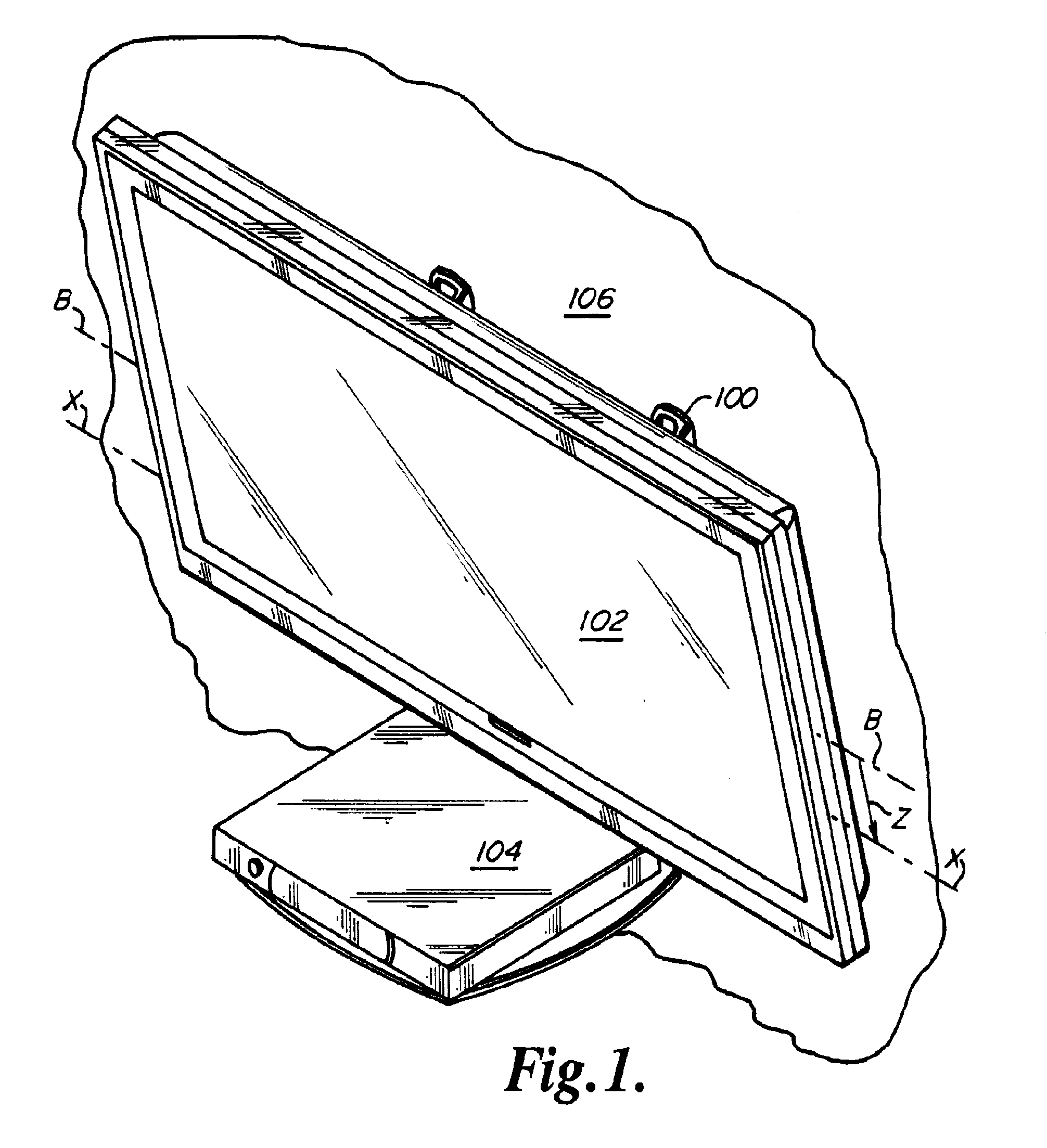
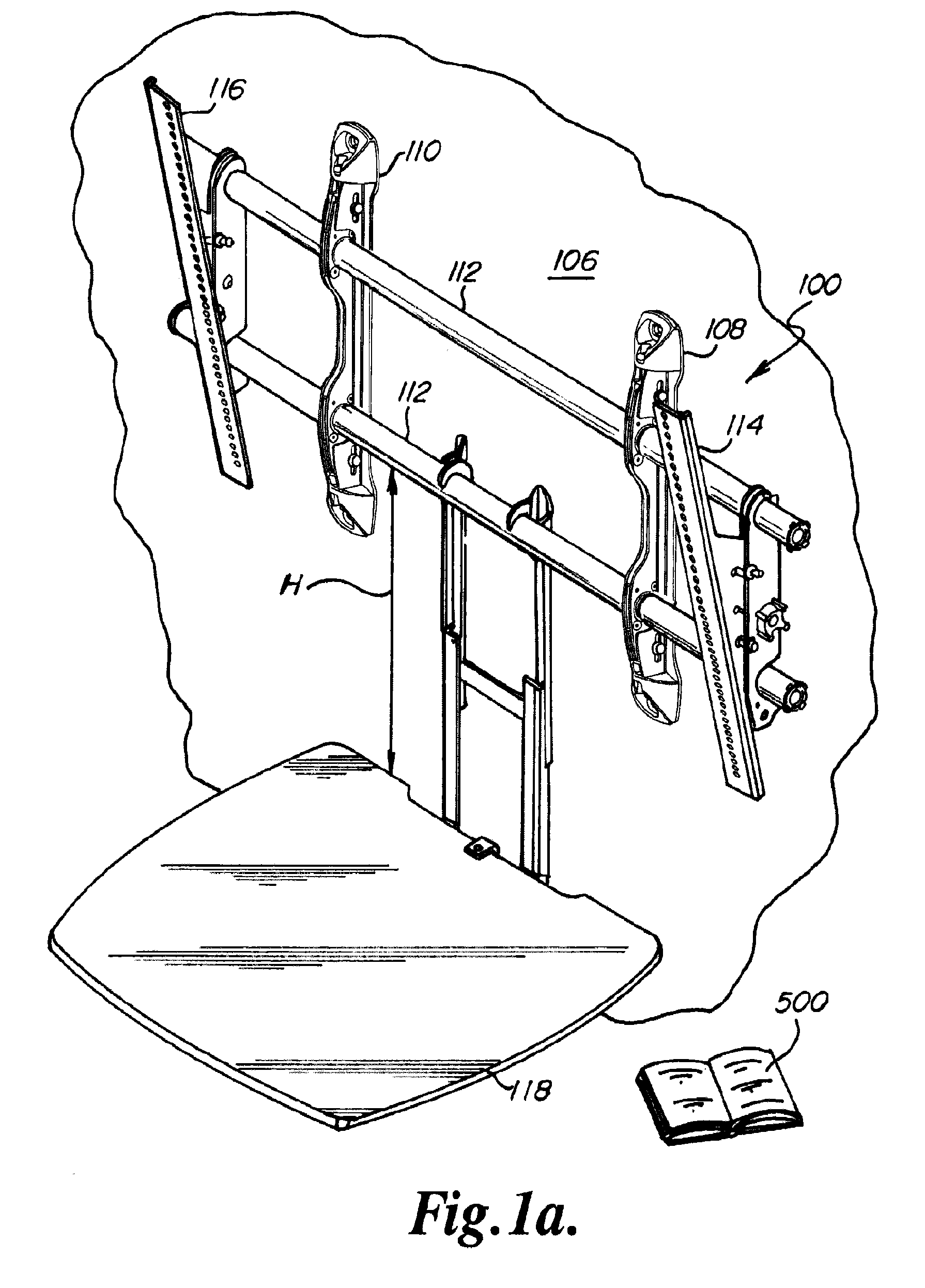
[0066]Mounting system 100 for mounting a flat panel electronic display 102, and optionally a peripheral device such as a DVD player 104, on a wall 106 is depicted generally in FIGS. 1 and 1A. Mounting system 100 generally includes wall brackets 108, 110, cross-supports 112, display interface brackets 114, 116, and shelf assembly 118.

[0067]As depicted generally in FIGS. 2-13, wall brackets 108, 110, are substantially identical and each generally includes mirror image guide members 120, 122, carrier assembly 124, and end caps 126, 128. Each guide member 120, 122, includes wall interface flange 130 with guide flange 132 projecting perpendicularly therefrom. Each wall interface flange 130 has an upper 134 and a lower 136 end portion, each defining an elongate rounded notch 138. When inwardly extending portions 140, 142, of guide member 120 are registered and mated with inwardly extending portions 140, 142, of guide member 122, the guide flanges 132 of guide members 120, 122, are spaced ...


PUM


Abstract

A display mount with post-installation adjustment features according to embodiments of the present disclosure addresses the above-mentioned needs of the industry. The mount may include two or more wall brackets, each having a vertically shiftable carrier assembly. Cross-supports extend between the carrier assemblies and are received in floating connection structures in the carriers. An electronic display display is coupled with the cross-supports. The carrier assembly of each wall bracket is independently vertically shiftable to shift the orientation of the cross-supports, and thereby adjust the vertical position and orientation of the electronic display device coupled with the cross-supports. The electronic display may be coupled to the cross-supports with display interface brackets which are tilt-adjustable to change the tilt position of the display device.

Description

RELATED APPLICATIONS[0001]This application claims the benefit of U.S. Provisional Application No. 61 / 019,104, entitled DISPLAY MOUNT WITH POST-INSTALLATION ADJUSTMENT FEATURES, filed Jan. 4, 2008, and further claims priority to U.S. Design Application No. 29 / 319,787, entitled TWO-RAIL MOUNT FOR ELECTRONIC DISPLAY, filed Jun. 15, 2008, U.S. Design Application No. 29 / 319,788, entitled SHELF ATTACHMENT FOR ELECTRONIC DISPLAY MOUNT, filed Jun. 15, 2008, U.S. Design Application No. 29 / 319,789, entitled WALL INTERFACE FOR DISPLAY MOUNT, filed Jun. 15, 2008, U.S. Design Application No. 29 / 319,790, entitled TILT ADJUSTABLE DISPLAY INTERFACE BRACKET, filed Jun. 15, 2008, and U.S. Design Application No. 29 / 319,792, entitled FIXED TWO-RAIL MOUNT FOR ELECTRONIC DISPLAY, filed Jun. 15, 2008, each of said applications hereby fully incorporated herein by reference.FIELD OF THE INVENTION[0002]The present invention relates generally to mounting devices for electronic displays and more particularly, ...

Claims


Application Information

Patent Timeline
Patent Type & Authority Applications(United States)
IPC IPC(8): G06F1/16H05K7/14
CPCF16M11/10F16M11/24G06F1/1601F16M2200/022F16M13/02
Inventor BREMMON, JEFFBRANDT, JAMIE
Owner LEGRAND AV INC
Why Eureka
Try Eureka