
Hidden drain system

Inactive Publication Date: 2011-03-10
HICKS JOHN E
View PDF13 Cites 6 Cited by
  • Summary
  • Abstract
  • Description
  • Claims
  • Application Information

AI Technical Summary

Benefits of technology

The present invention in several embodiments is an arrangement of components that work together to hide the attachment screws for drainage channels behind the exterior siding. The drain exit for this system is larger for a greater volume of runoff. This helps reduce and / or eliminate wood wrought of the roof top eaves caused by traditional exterior wall-mounted drainage systems. The entire corner cap is preferably an open channel. There is preferably a left side and a right side application. Preferably a spray on rubberized coating is applied to the surface contacting the wall of the building to prevent water from damaging the building. This system is ideal for any residential and most commercial uses.

Problems solved by technology

Downspout drainpipes, brackets, straps and screws can often be bulky and unattractive.
Traditional gutter and drain systems often clog and don't properly drain water if not constantly maintained.
This may be due to the drainpipe being weighed down by debris, such as leaves and branches.
These items flow downward and typically clog up the pipe's sharp elbows.
The drains and gutters used are often made of thin gauged metal with is easily damaged and kinked thus causing further problems.

Method used


Image

  • Hidden drain system
  • Hidden drain system
  • Hidden drain system

Examples


Embodiment Construction

Prior to proceeding to the more detailed description of the present invention it should be noted that, for the sake of clarity and understanding, identical components which have identical functions have been identified with identical reference numerals throughout the several views illustrated in the drawing figures.

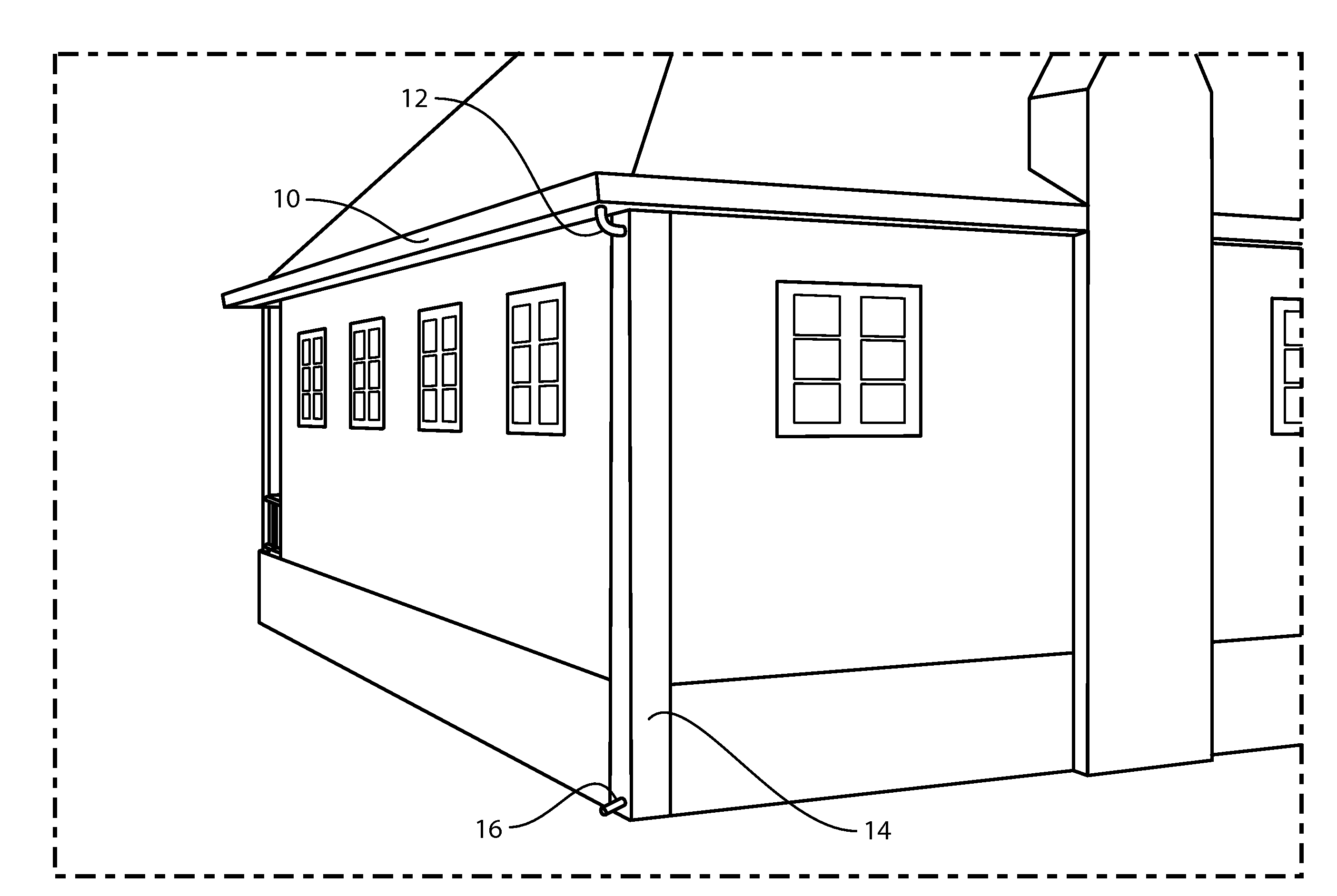
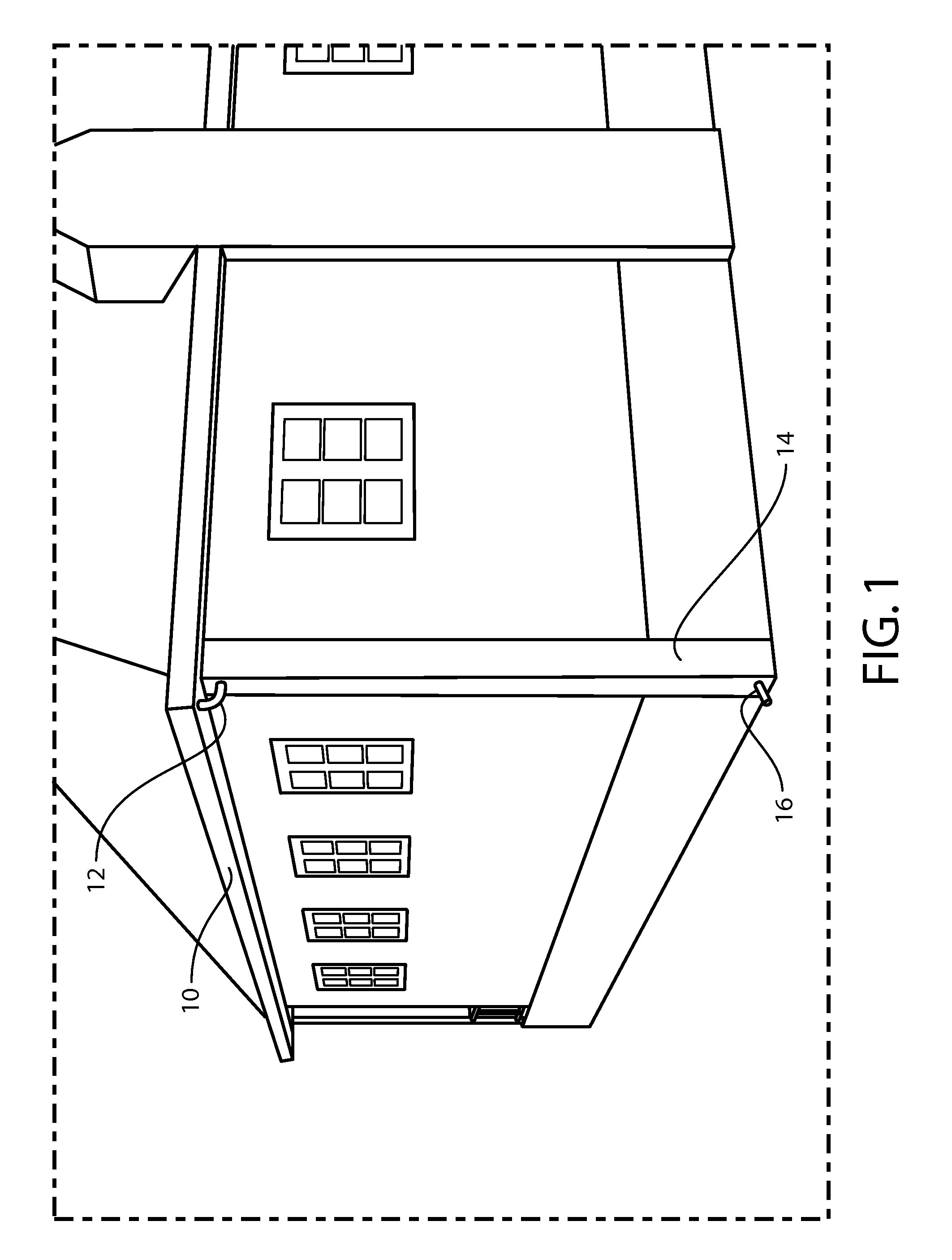
Reference is now made, more particularly, to FIG. 1 which is a general perspective view drawing of a preferred embodiment of the present invention installed on a home. The present invention is a drainage system comprising a gutter 10, service elbow 12, corner cap with drainage channel 14 and drain spout 16.

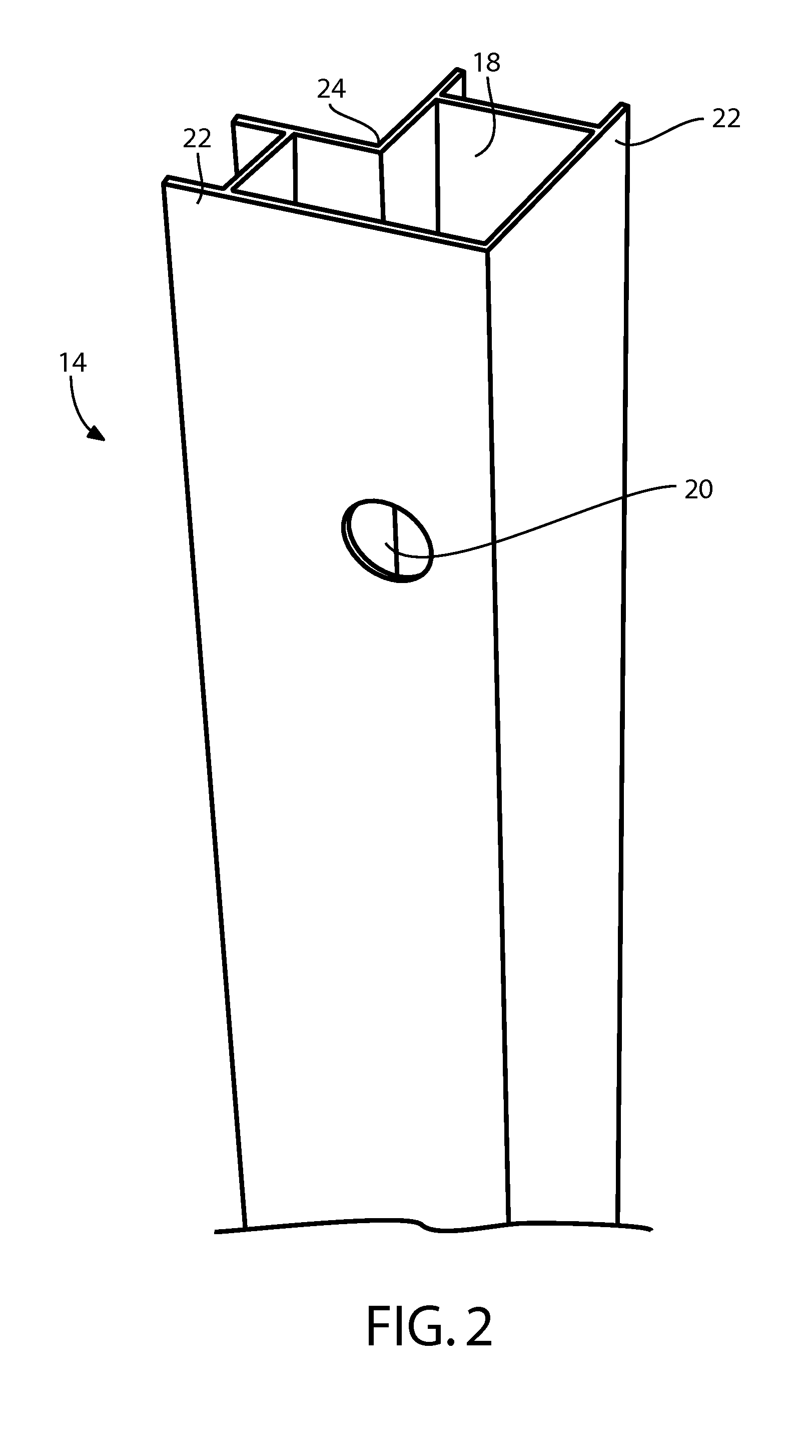
Reference is now made, more particularly, to FIG. 2 which is a general perspective drawing of a preferred embodiment of a corner cap with a drainage channel. Corner cap 14 with drainage channel 18 is shown. Corner cap comprises drainage channel 18, service elbow input 20, overhangs 22 and building securing surface 24. Service elbow input 20 is an opening for accepting a...


PUM


Abstract

The present invention in several embodiments is an arrangement of components that work together to hide the attachment screws for drainage channels behind the exterior siding. The drain exit for this system is larger for a greater volume of runoff. This helps reduce and / or eliminate wood wrought of the roof top eaves caused by traditional exterior wall-mounted drainage systems. The entire corner cap is preferably an open channel. There is preferably a left side and a right side application. Preferably a spray on rubberized coating is applied to the surface contacting the wall of the building to prevent water from damaging the building. This system is ideal for any residential and most commercial uses.

Description

FIELD OF THE INVENTIONThe invention is related to building gutter and drain systems. The present invention is particularly applicable to gutter and drain systems for residential and commercial buildings.BACKGROUND OF THE INVENTIONDownspout drainpipes, brackets, straps and screws can often be bulky and unattractive. Traditional gutter and drain systems often clog and don't properly drain water if not constantly maintained. This may be due to the drainpipe being weighed down by debris, such as leaves and branches. These items flow downward and typically clog up the pipe's sharp elbows. Additionally, traditional metal gutter and drain systems use screwed-on brackets and straps with screws to secured the system to a building. The drains and gutters used are often made of thin gauged metal with is easily damaged and kinked thus causing further problems.Accordingly, it has been considered desirable to develop a new and improved gutter and drainage system which would overcome the foregoing...

Claims


Application Information

Patent Timeline
IPC IPC(8): E04D13/08
CPCE04D13/0767E04D2013/086E04D13/08
Inventor HICKS, JOHN E.
Owner HICKS JOHN E
Learn More