Bullet trap

Active Publication Date: 2011-03-10
THALES AUSTRALIA
View PDF11 Cites 12 Cited by
  • Summary
  • Abstract
  • Description
  • Claims
  • Application Information

AI Technical Summary

Benefits of technology

[0005]Therefore, according to a first broad aspect of the present invention there is provided A bullet trap comprising a hollow body for connecting to a muzzle end of a weapon that can fire a bullet, the body having a chamber into which a bullet can be fired, said chamber having a io plurality of baffles located one behind the other in an aligned series arrangement and being for absorbing the kinetic ene

Problems solved by technology

The resulting gas pressure, in turn, launches the rocket and may even detonate the rocket for continued flight.
Known bullet tr

Method used


Image

  • Bullet trap
  • Bullet trap
  • Bullet trap

Examples


Embodiment Construction

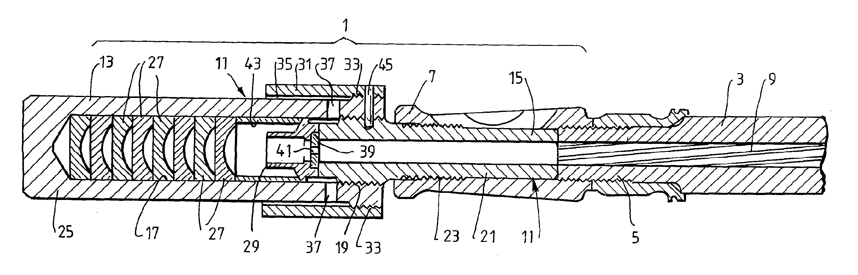
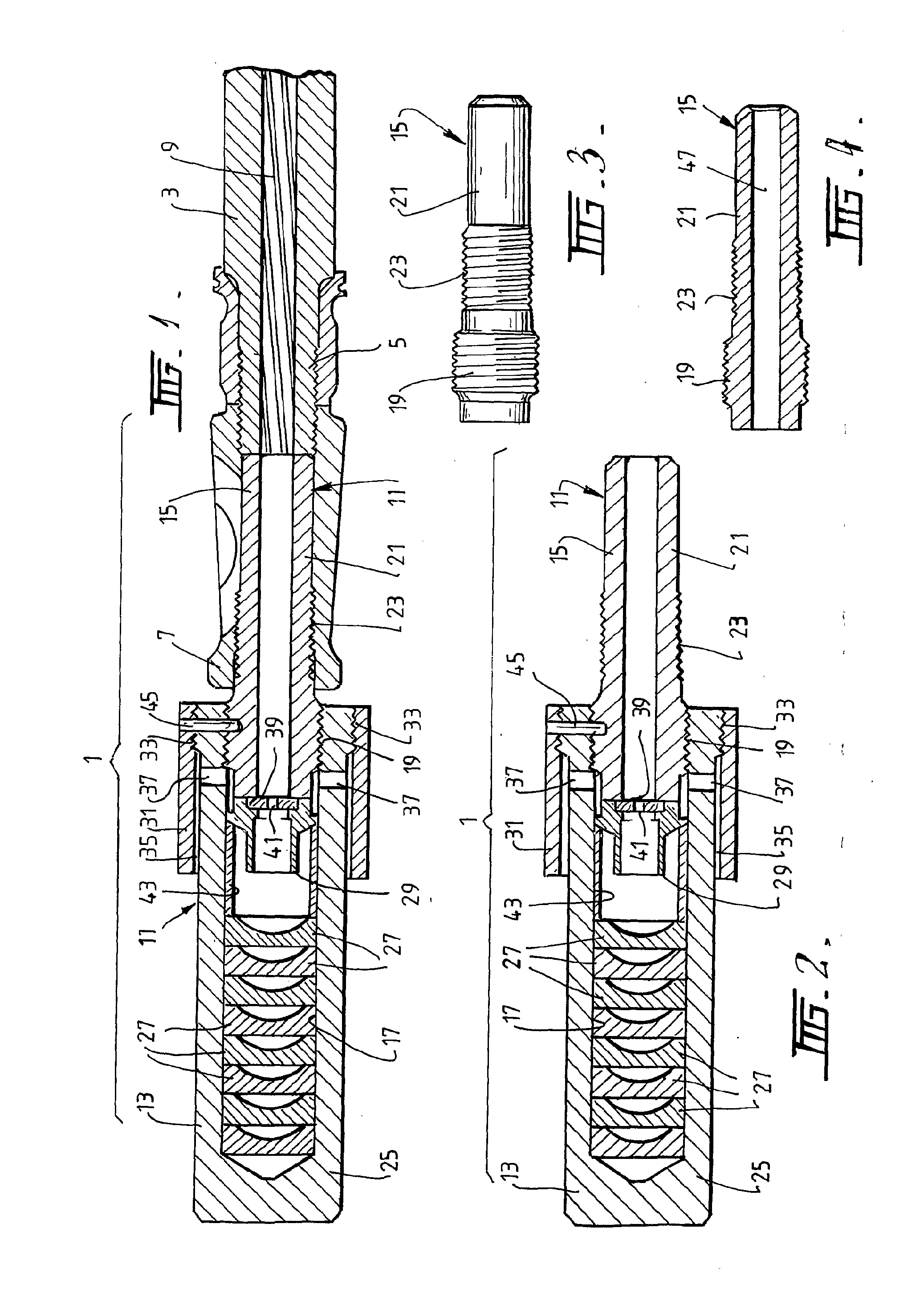
[0029]Referring firstly to FIGS. 1 and 2, it can be seen that the example bullet trap 1 is fitted to the end of a weapon such as a rifle 3, at the muzzle end 5. The weapon typically contains a muzzle 7 that is screw threadably fastened to the muzzle end 5 of the weapon 3. The weapon 3 has a central longitudinally extending bore 9 that may be riffled in a conventional manner. The longitudinal central axis of the bore 9 coincides with a central longitudinal axis of the bullet trap 1. Typically, the bullet trap 1 is of circular transverse cross section, however, other transverse cross sectional shapes are not excluded. The bullet trap 1 has a body 11 comprised of one part 13 and another part 15. The one part 13 has a chamber 17 therein into which a bullet can be fired from the weapon 3. The one part 13 and the other part 15 are releasably screw threadably attached to each other by screw threads 19. The chamber 17 is elongate and is aligned along the central longitudinal axis of the bor...


PUM


Abstract

A bullet trap (1) is provided that connects to a muzzle end (5) of a weapon (3). The bullet trap (1) has a body (11) with a chamber (17) into which a bullet can be fired. The chamber (17) has a plurality of baffles (27) located one behind the other in an aligned series arrangement. The baffles (27) absorb kinetic energy of a fired bullet and enable the bullet to be trapped within the body (11). The baffles (27) have a thickness at a centre of axis of travel of a bullet less than the thickness at a radially outwardly distant position to provide for a deformation at the centre of a first of a series of baffles (27) before there will be engagement of a centre of second and subsequent baffles (27).

Description

RELATED APPLICATIONS[0001]This application is based on and claims the benefit of the filing dates of Australian provisional application 2007902058 filed 19 Apr. 2007, and U.S. provisional application 60 / 944136 filed 15 Jun. 2007 the contents of which are incorporated herein their entirety.FIELD OF THE INVENTION[0002]This invention relates to a Bullet Trap and relates particularly but not exclusively to a bullet trap for use with weapons that are used in military or like applications.BACKGROUND[0003]Hitherto, bullet traps have been known. In some cases, bullet traps are provided for use with rocket launchers in order to capture a bullet that is fired with the rocket launcher and used as a consequence of the detonation to generate gas pressure for the launching of the rocket. Desirably, the bullet is not required to travel with the rocket and is therefore captured. The resulting gas pressure, in turn, launches the rocket and may even detonate the rocket for continued flight. In other ...

Claims


Application Information

Patent Timeline
IPC IPC(8): F41A21/32F41J13/00
CPCF41A21/26F42B30/06F41A21/32
Inventor KENNEDY, BRUCEMALONEY, DAVID JOHNPEARCE, TREVOR JOHN
Owner THALES AUSTRALIA
Why Eureka
Try Eureka