
Cylinder cube

a cylinder and cube technology, applied in the field of three-dimensional cylinder cubes, can solve problems such as less interesting

Inactive Publication Date: 2011-03-10
YANG CHIN HUANG
View PDF13 Cites 8 Cited by
  • Summary
  • Abstract
  • Description
  • Claims
  • Application Information

AI Technical Summary

Benefits of technology

"The invention is a cylinder cube. The technical effect of this invention is to provide a more efficient and compact solution for storing and transporting cylinders."

Problems solved by technology

However, it is less interesting.

Method used


Image

  • Cylinder cube
  • Cylinder cube
  • Cylinder cube

Examples


Embodiment Construction

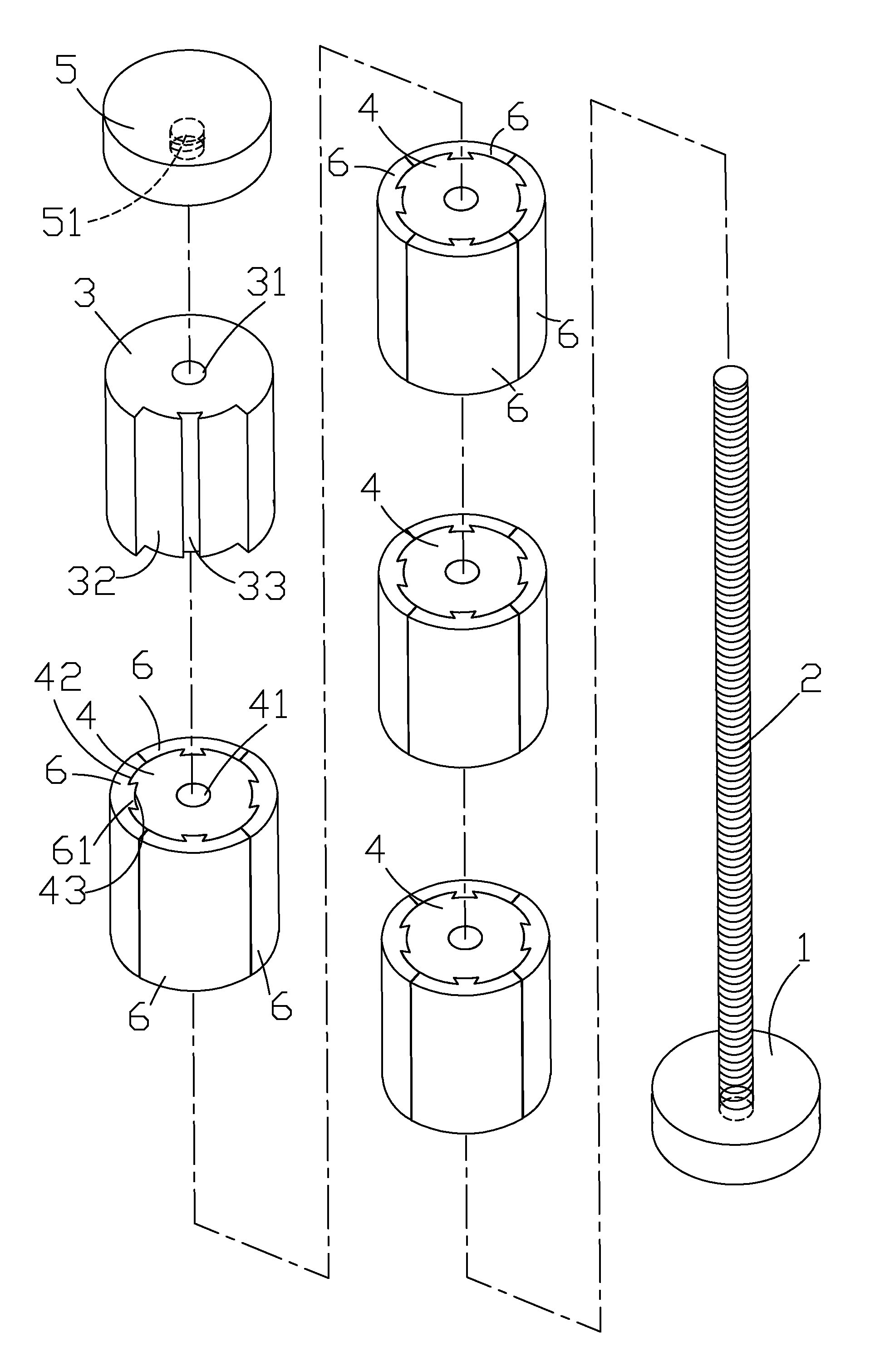
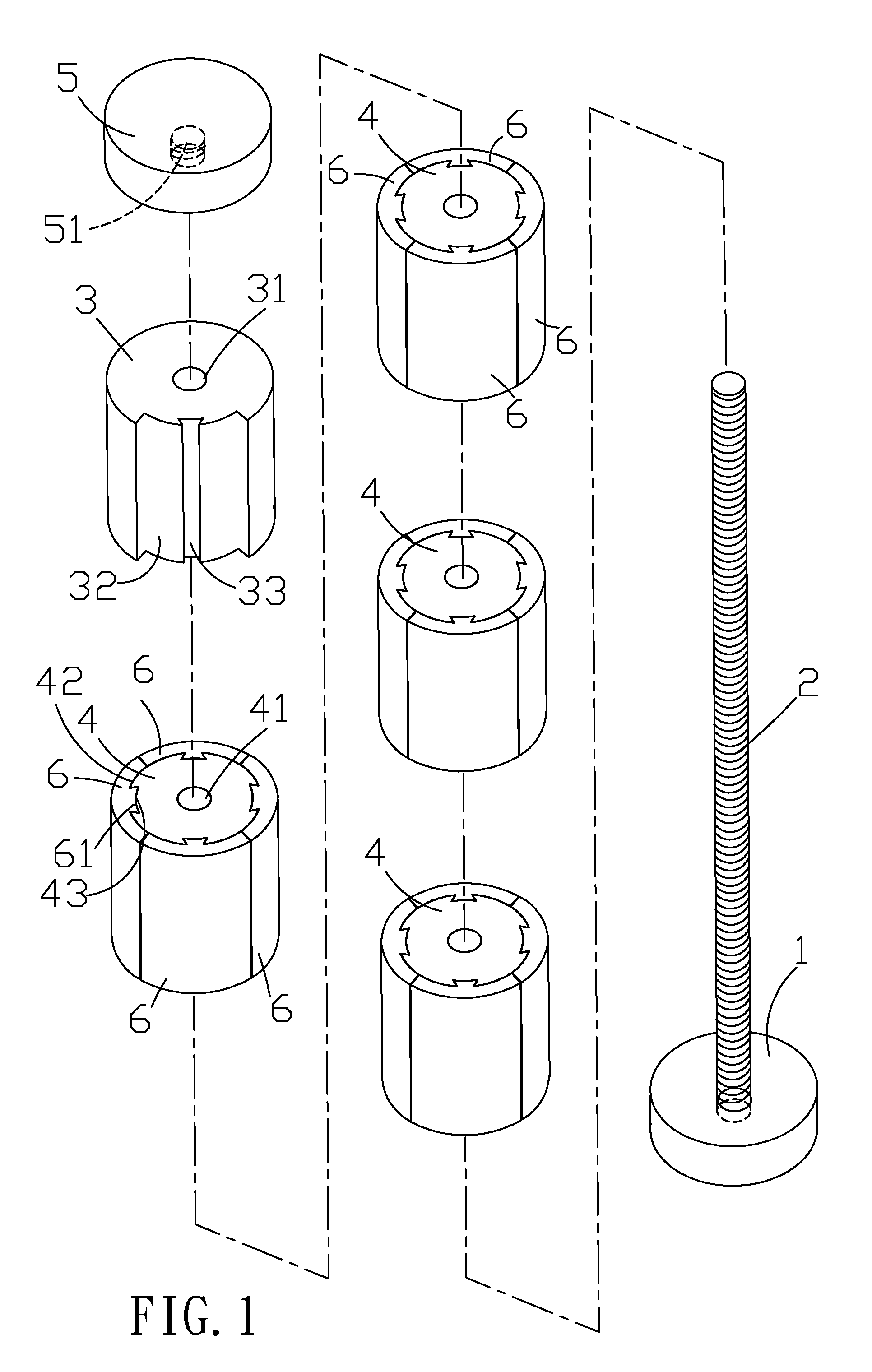
[0017]Referring to FIGS. 1 to 4, a cylinder cube in accordance with a first preferred embodiment of the invention is shown. The cylinder cube comprises the following components as discussed in detail below.

[0018]A disc shaped base 1 has a threaded shank 2 extending from one surface. A plurality of cylindrical units 4 each comprises an axial bore 41 rotatably put on the shank 2, four lengthwise sliding faces 42 equally spaced apart around an outer surface, and four lengthwise sliding grooves 43 equally spaced apart around the outer surface in which each sliding groove 43 is disposed between two adjacent ones of the sliding faces 42. The units 4 are formed of plastic.

[0019]A plurality of arc shaped sliding blocks 6 are formed of plastic. The sliding block 6 comprises a lengthwise dovetail 61 on an inner surface adapted to fit into the sliding groove 43 for interlocking the sliding block 6 and the unit 4 in which the remaining portion of the inner surface of the sliding block 6 is enga...


PUM


Abstract

A cylinder cube in one embodiment includes a disc base having an extending threaded shank; four cylindrical units each rotatably put on the shank and comprising four lengthwise sliding faces spaced around an outer surface, and four lengthwise sliding grooves each formed between two sliding groove; a plurality of arc shaped sliding blocks each comprising a lengthwise dovetail on an inner surface fit into the sliding groove; a cylindrical manipulation block rotatably put on the shank and comprising a lengthwise sliding recess on an outer surface and two lengthwise troughs on both sides of the sliding recess, the troughs and the sliding recess together forming a shape complementary to a shape of the sliding block, and the manipulation block sized as a combination of the unit and the sliding blocks assembled thereon; and a disc head threadedly secured to the shank.

Description

BACKGROUND OF THE INVENTION[0001]1. Field of Invention[0002]The invention relates to combination puzzles and more particularly to a three-dimensional cylinder cube with improved characteristics.[0003]2. Description of Related Art[0004]There are many different puzzles known. One type of puzzle is fifteen puzzle which is a two-dimensional puzzle. However, it is less interesting. Thus, continuing improvements in the exploitation of puzzle are constantly being sought.SUMMARY OF THE INVENTION[0005]It is therefore one object of the invention to provide a cylinder cube.[0006]The above and other objects, features and advantages of the invention will become apparent from the following detailed description taken with the accompanying drawings.BRIEF DESCRIPTION OF THE DRAWINGS[0007]FIG. 1 is an exploded view of a first preferred embodiment of cylinder cube according to the invention;[0008]FIG. 2 is a perspective view of the assembled cylinder cube;[0009]FIG. 3 is an exploded view of one unit a...

Claims


Application Information

Patent Timeline
Patent Type & Authority Applications(United States)
IPC IPC(8): A63F9/08
CPCA63F9/0865
Inventor YANG, CHIN-HUANG
Owner YANG CHIN HUANG
Learn More