Inverter

a technology of inverter and gate driver, which is applied in the direction of pulse technique, process and machine control, instruments, etc., can solve the problems of increasing power loss in the power switch, reducing component costs compared to other solutions, and difficulty in cost-effectively generating the auxiliary voltage needed by the gate driver

Active Publication Date: 2011-03-31
ABB (SCHWEIZ) AG
View PDF1 Cites 27 Cited by
  • Summary
  • Abstract
  • Description
  • Claims
  • Application Information

AI Technical Summary

Benefits of technology

This patent describes an inverter with multiple semiconductor switches controlled by a control circuit. The control circuit includes three bootstrap circuits which use different auxiliary voltages to drive each individual switch's driver. By providing separate boosted sources for each driver, this ensures consistent performance across all the switches even if one source fails.

Problems solved by technology

Technical problem: The technical problem addressed in this patent relates to generating a reliable and efficient negative auxiliary voltage for the gate driver of a power semiconductor in an inverter system that prevents unintended turning on of components resulting in reduced power efficiency and increased power loss.

Method used


Image

  • Inverter
  • Inverter
  • Inverter

Examples


Embodiment Construction

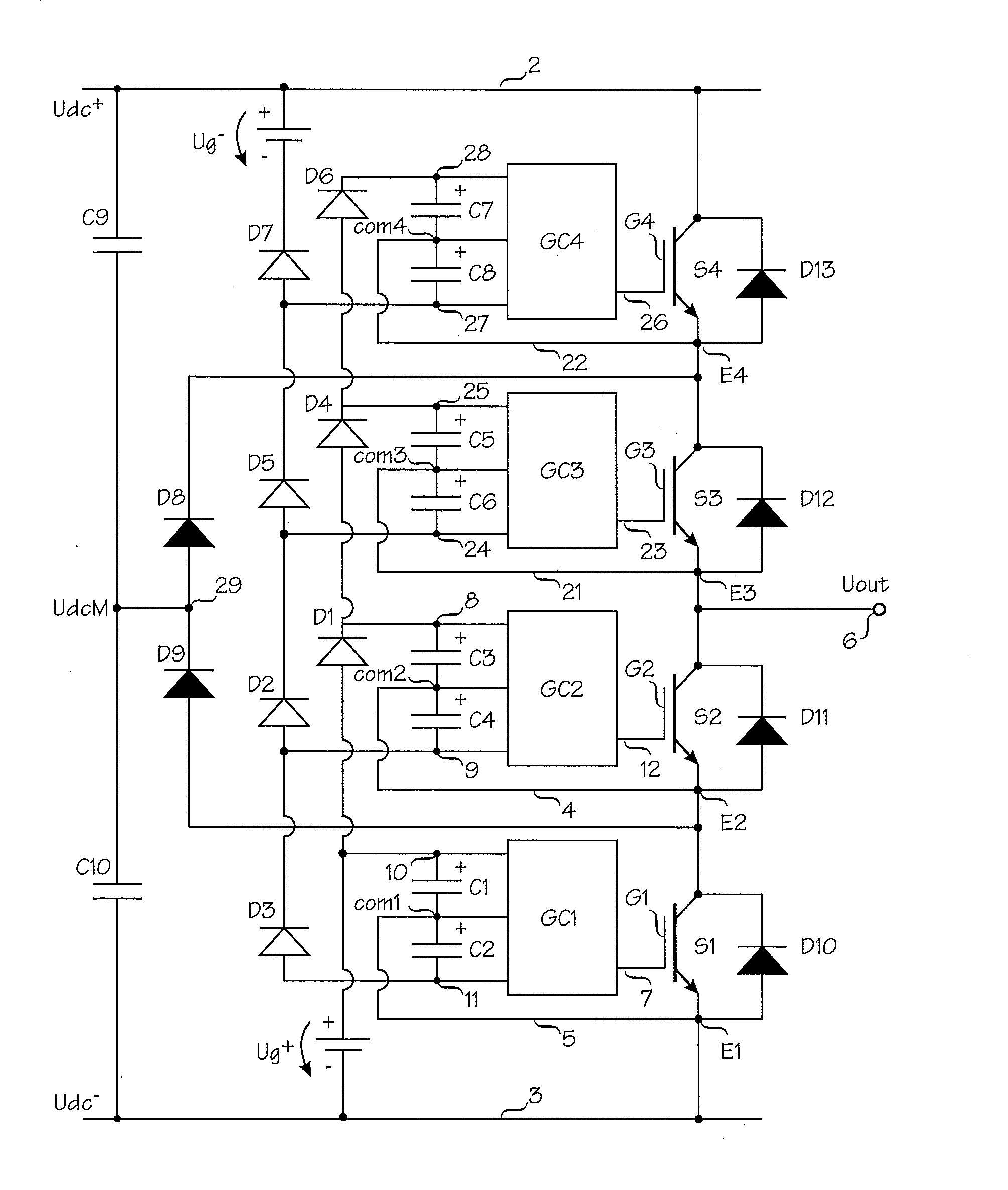
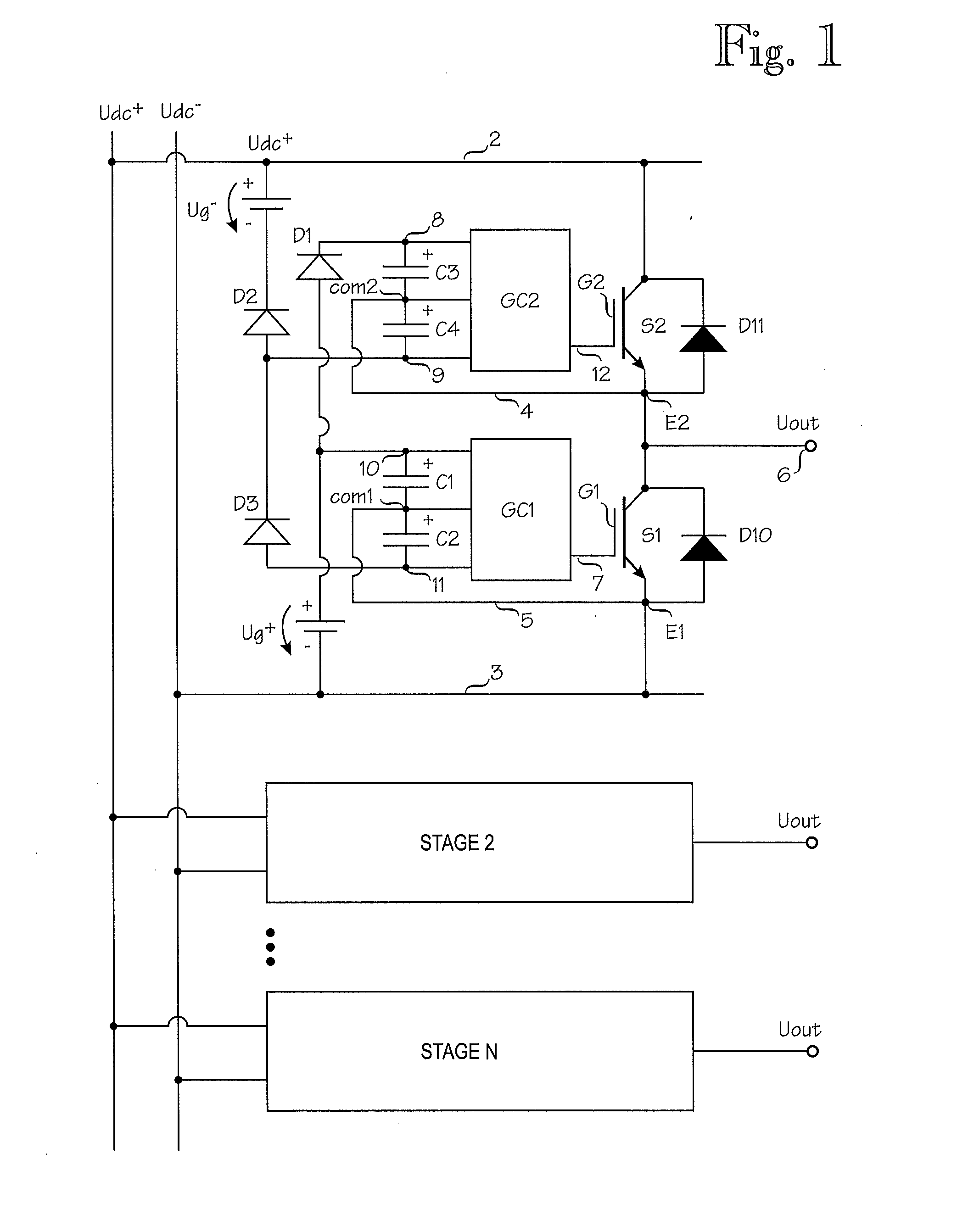
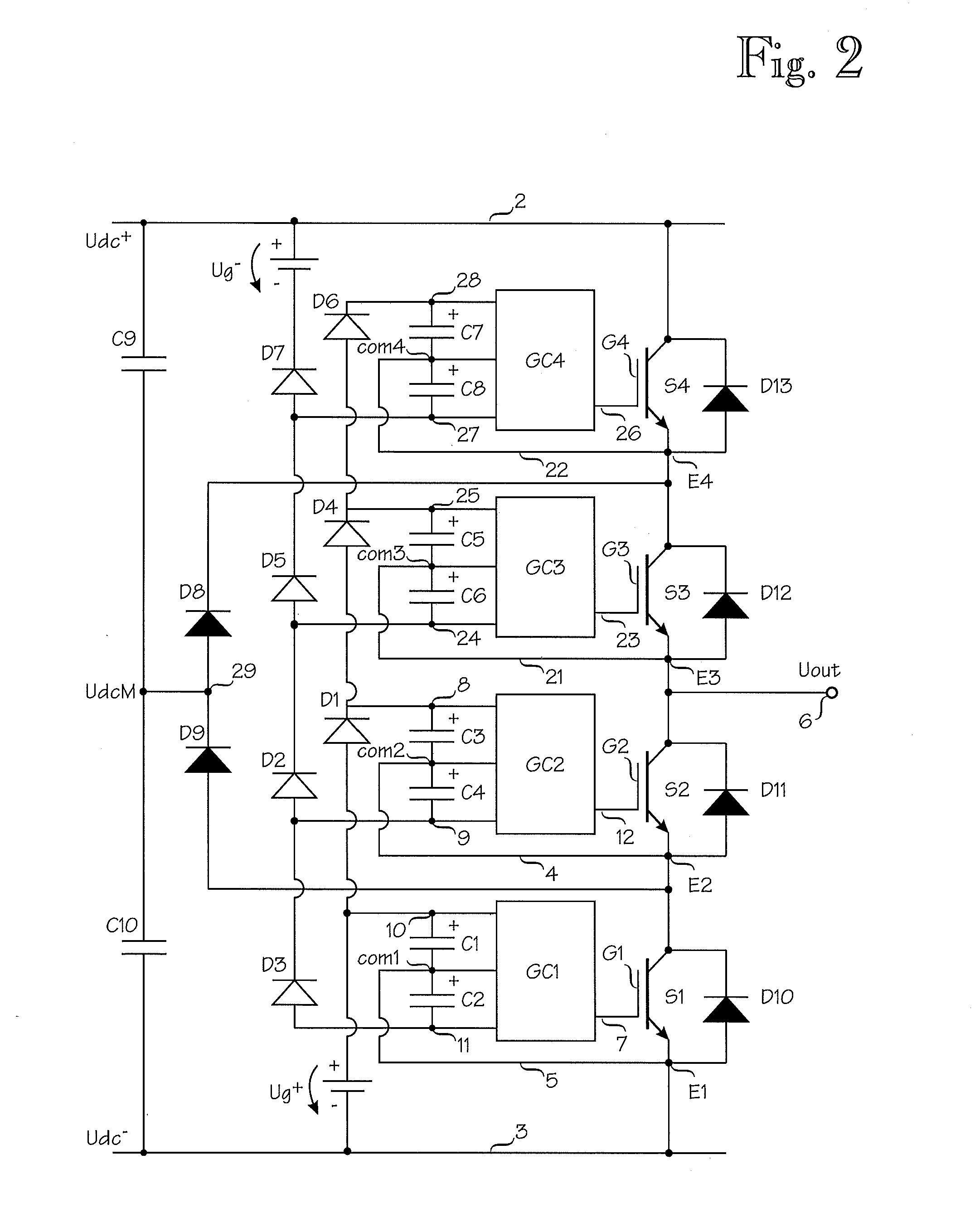
[0015]An inverter according to exemplary embodiments disclosed herein provides a novel bootstrap technique for controlling a two-level or multi-level inverter. A bootstrap technique can be utilized to provide at least one further bootstrapped negative auxiliary voltage to a switch driver of at least one semiconductor switch from at least one bootstrapped negative auxiliary voltage already formed by the bootstrap technique, the further bootstrapped negative auxiliary voltage being referenced to the common potential of the respective switch driver. The new bootstrap structure enables the generation of both the positive auxiliary voltage and the negative auxiliary voltage for the switch drivers of the power semiconductors.

[0016]At the start up of an inverter, the inverter can be configured to perform a startup sequence to provide auxiliary voltages to the auxiliary voltage inputs of the switch drivers by turning the power semiconductors sequentially on and off. As disclosed herein, a s...


PUM


Abstract

A two-level or multi-level inverter are supplied with a positive auxiliary voltage (Ug+) and a negative auxiliary voltage (Ug−). A bootstrap technique provides a first positive auxiliary voltage and a first negative auxiliary voltage from the supplied potentials. The bootstrap technique provides at least one additional negative auxiliary voltage to a switch driver of at least one semiconductor switch from the first negative auxiliary voltage. At the start up of an inverter, the inverter can perform a startup sequence to provide auxiliary voltages to the respective auxiliary voltage inputs of the switch drivers by turning the power semiconductors sequentially on and off.

Description


Claims


Application Information

Patent Timeline
Owner ABB (SCHWEIZ) AG
Why Eureka
Try Eureka