[0005]The main body in the above structure is formed to be
thin walled-strip-shaped, which enables the main body in the support equipment for measuring optical nerve-activity to be lightweight. In accordance with the present invention, it is preferable to use small
diameter-optical fibers. More specifically, as described in the claim 2, it is preferable to use flexible optical fibers whose
diameter is 0.5 mm or less. As for the main body including the optical fibers, the thickness may be 1 mm or less and the weight may be 50 g or less / m, or 30 g / m preferably. Various sorts of materials such as resin film or paper (Japanese paper) may be employed as the main body-materials if they are
thin walled, lightweight, flexible, and have hard-to-rupture-
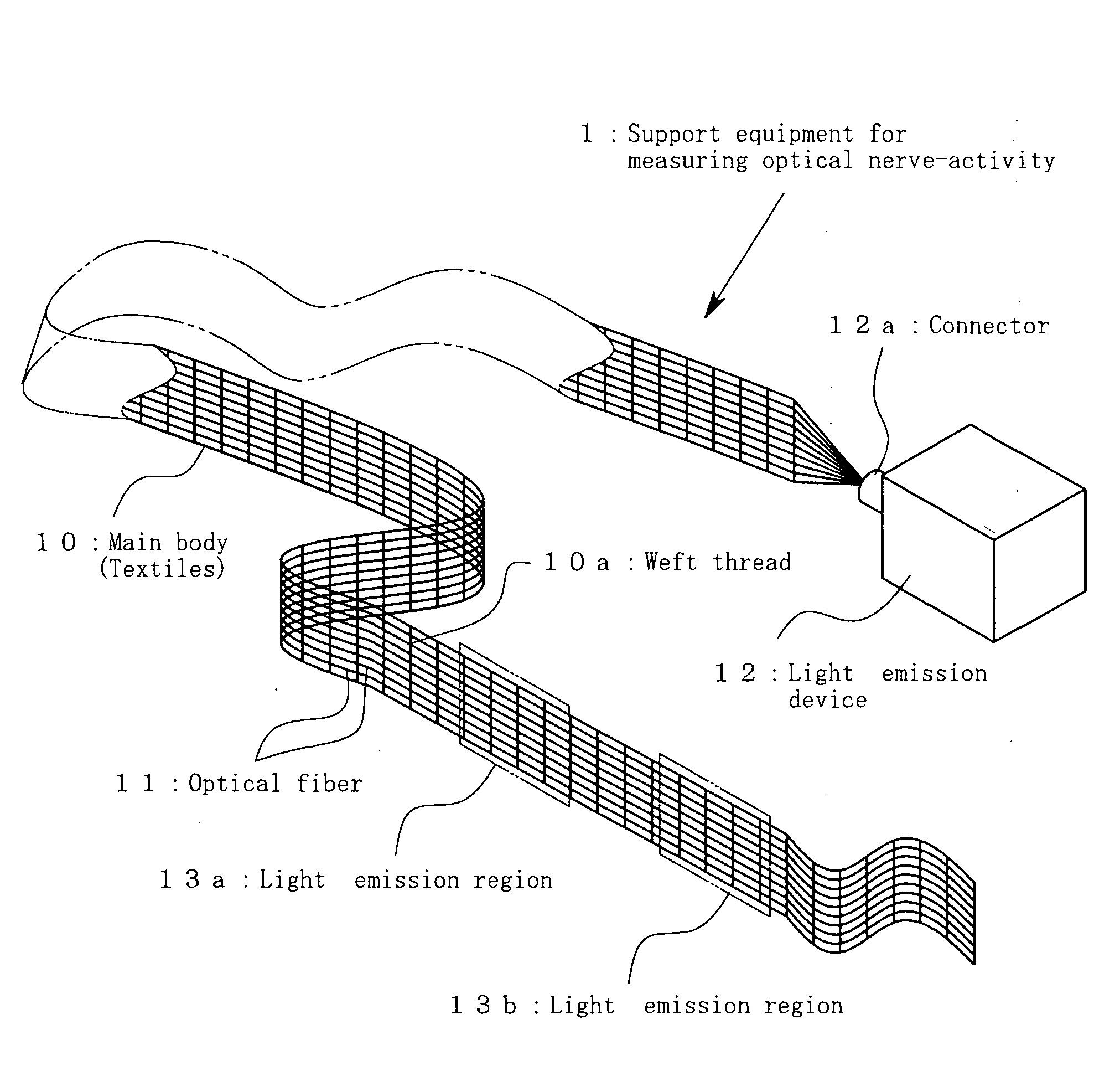
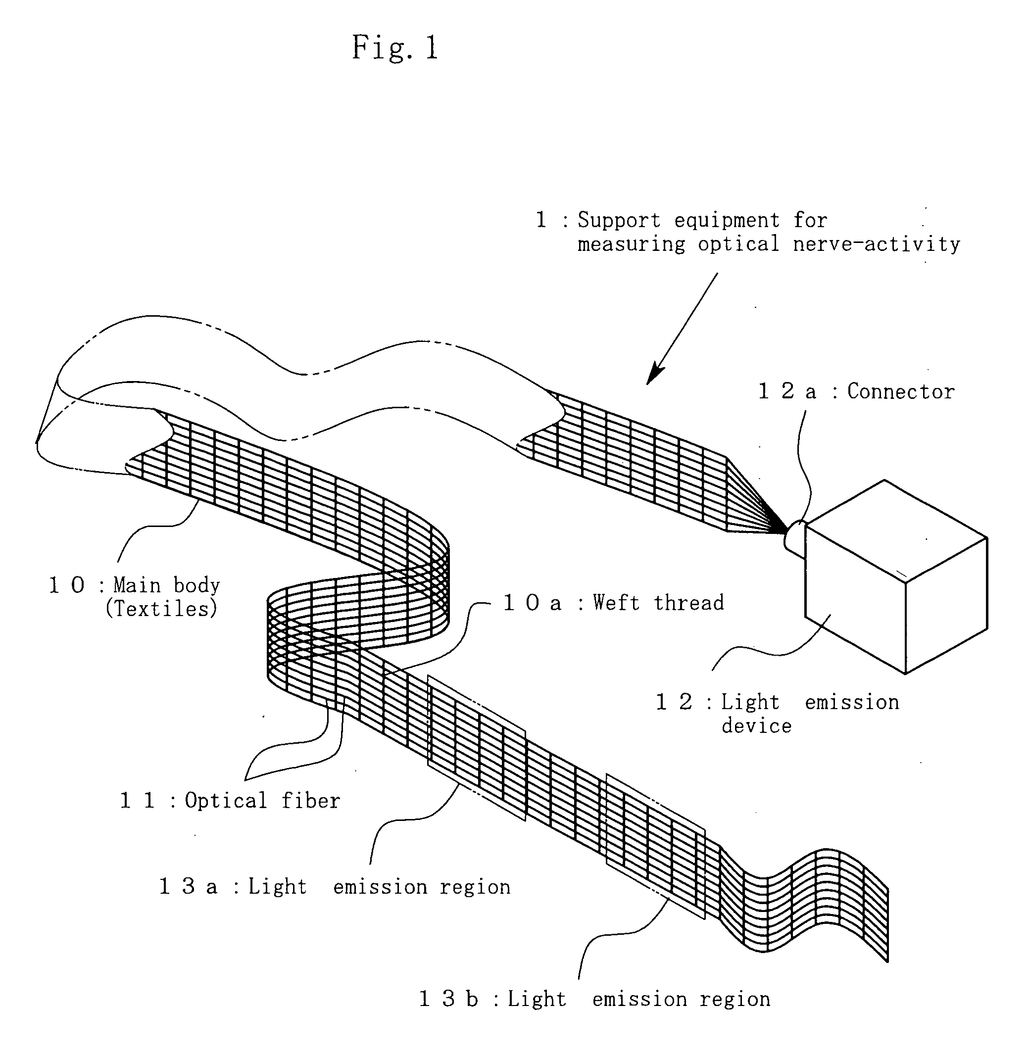
solidity and they can join the plurality of optical fibers. In accordance with the present invention, as described in the claim 3, it is favorable to use the main body which is made of a cloth whose warp threads in the longitudinal direction are partially or all replaced with the above mentioned-optical fibers. In this case, the cloth may be woven with the weft-threads less densely so as to prevent the optical fibers from warping with the weft threads. Such a weaving manner can increase the light-propagation-efficiency.
[0006]The above mentioned-plurality of light leak parts formed in the optical fibers should be the ones which irradiate a portion of light propagated in the optical fibers to the subject-eyes and whose lighting intensity is enough to make the subject brain wave-changes appear in a monitor along with the
light stimulation. In accordance with the present invention, as described in the claim 4, the light emission regions which evenly produce the light across the subject eyes with sufficient
light intensity were produced by making the light leak parts with
acute angle-incisions in the
optical fiber-
peripheral surfaces at various directions and intervals. Furthermore, In accordance with the present invention, as described in the claim 5, melting and
cutting of the optical fibers whose one ends were bundled enabled the light from the light emission-means to propagate efficiently. In this case, surfaces of the melted and
cut-one ends of the bundled-optical fibers may be polished.
[0007]In accordance with the present invention, as described in the claim 6, when a plurality of the light-emission-regions are made in a single main body, the light leak parts in the plurality of optical fibers positioned in parallel in one of the light emission regions should be formed in every other or every plurality of the optical fibers alternately with those in the other light emission region. In addition, in accordance with the present invention, as described in the claim 7, it is preferable the support equipment includes a plurality of the main bodies. This is because layering of the plurality of main bodies can provide sufficient
light intensity when the
light intensity provided by the single main body is insufficient. In this case, it is preferable to layer the plurality of main bodies keeping the
light propagation directions in the optical fibers same so that one ends of the layered main bodies are bundled only on one side of the subject-head region for avoiding the main bodies from being an obstacle for doctors and others in medical front such as operations and the like.
[0008]In the support equipment for measuring optical nerve-activity in accordance of the present invention, the optical fibers are joined in the main body which is thin-walled, lightweight, and flexible. Then, the main body is easily attached to the subject-head region; therefore, attaching of the main body to the subject-head region does not cause a long time-pressure to the subject-eyeballs. In addition, just attaching the main body to the subject-head region can fix its position; accordingly, attaching of the main body to the subject-head region does not cause the
pressure increase to the eyeballs. Furthermore, the main body is extremely lightweight; therefore, its position-off cannot occur during the long time-operations or its detachment can hardly occur during the operations. Moreover, employing the
optical fiber-woven-cloth makes it possible to
mass-produce the support equipment for measuring optical nerve-activity at low cost. Thus, the support equipment for measuring optical nerve-activity in accordance of the present invention can lessen the burdens on either the subjects such as patients and the like or doctors and the like and provide the easy handling-support equipment for measuring optical nerve-activity at low cost. Furthermore, the main body is a
single use-type and the feature of the support equipment can provide the support equipment for measuring optical nerve-activity with high level-safety.

