Wireless power feeder and wireless power transmission system

a technology of wireless power transmission system and wireless power feeder, which is applied in the direction of transformer/inductance circuit, circuit arrangement, inductance, etc., can solve the problem of not being able to feed big electric power

Active Publication Date: 2011-04-07
TDK CORPARATION
View PDF3 Cites 66 Cited by
  • Summary
  • Abstract
  • Description
  • Claims
  • Application Information

AI Technical Summary

Benefits of technology

[0023]The present invention makes it easy to allow the drive frequency to track the re...

Problems solved by technology

The type (B) utilizing radio wave is available in ...

Method used


Image

  • Wireless power feeder and wireless power transmission system
  • Wireless power feeder and wireless power transmission system
  • Wireless power feeder and wireless power transmission system

Examples


first embodiment

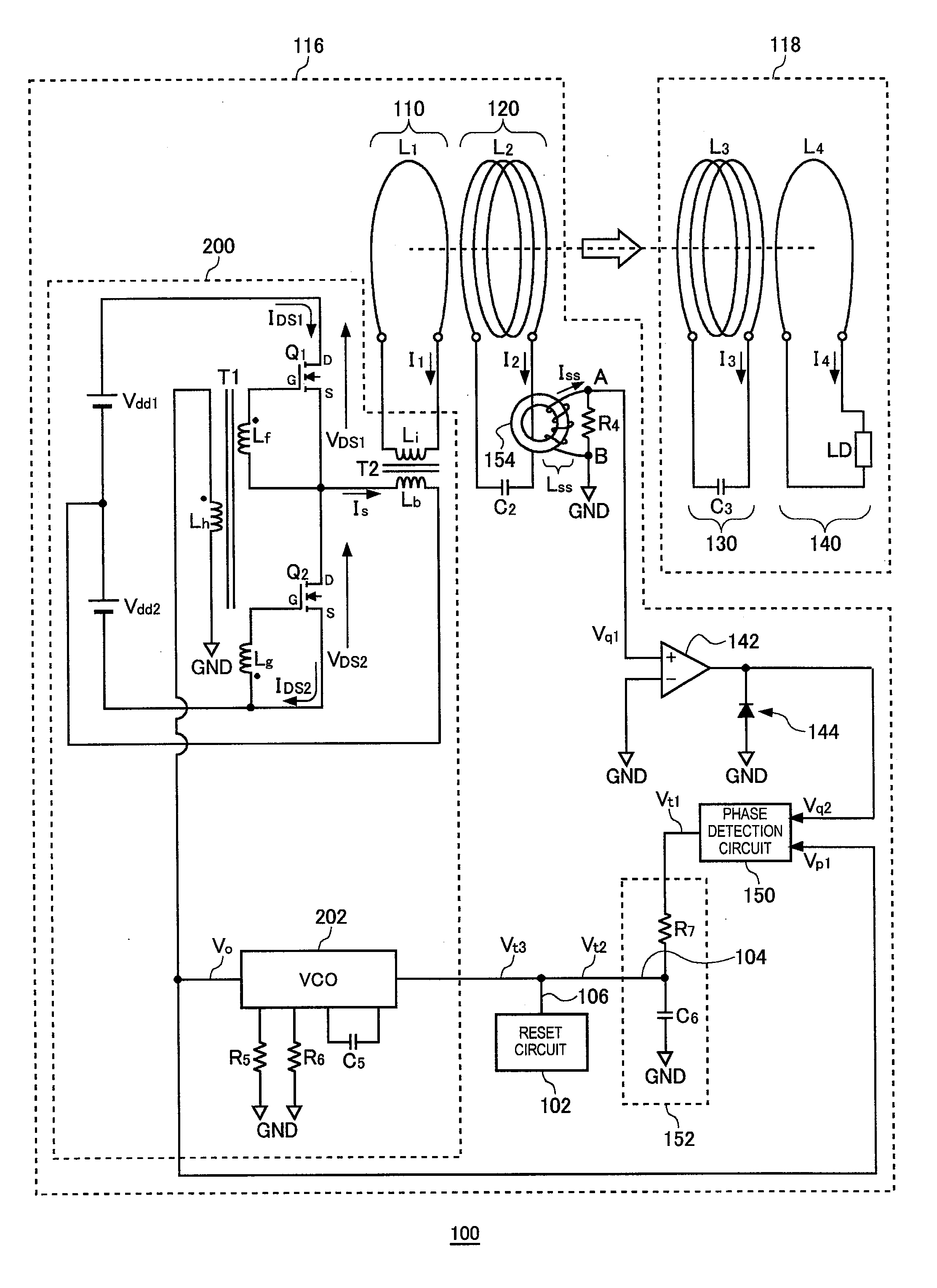
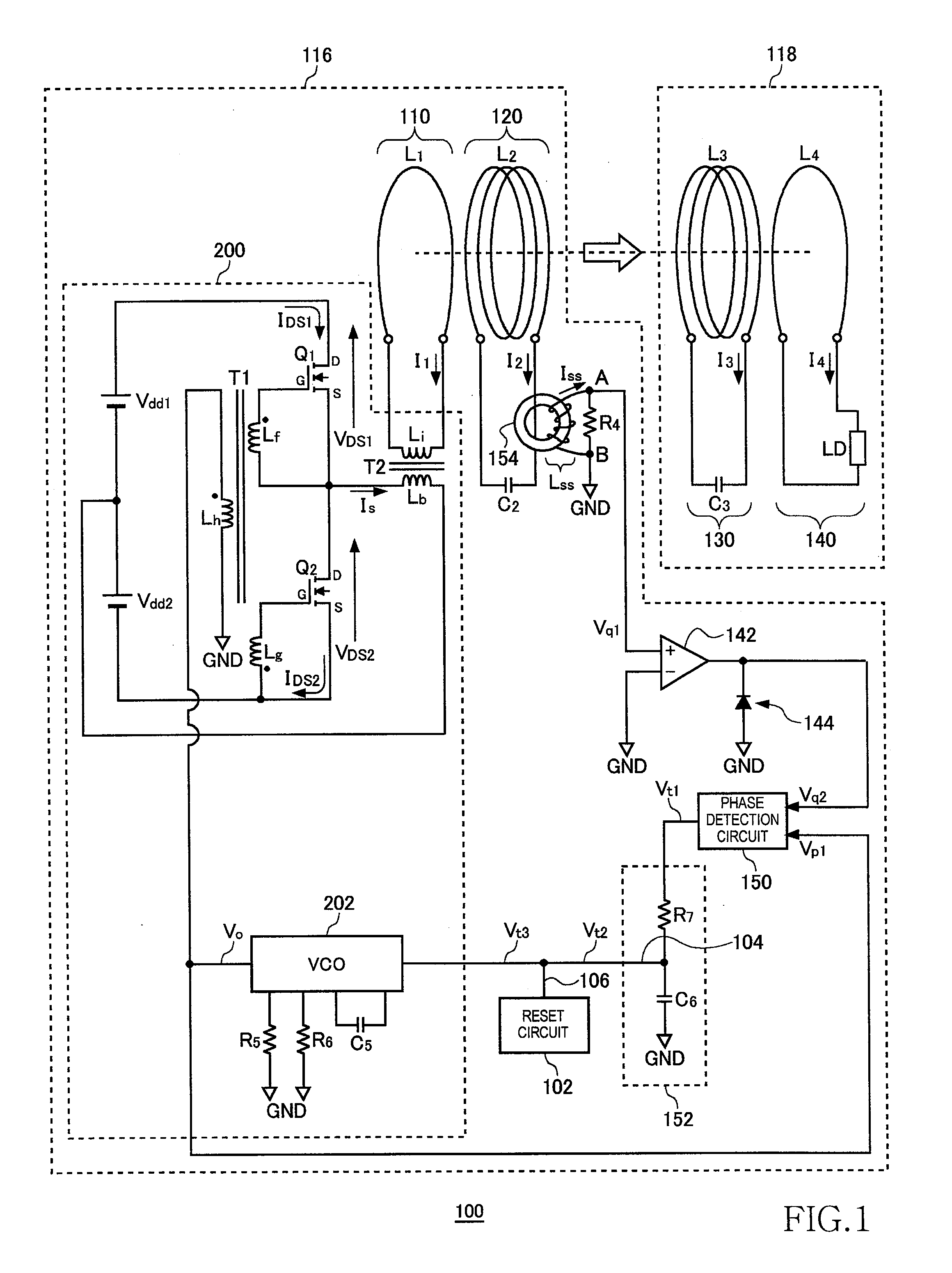
[0037]FIG. 1 is a system configuration view of a wireless power transmission system 100 according to the first embodiment. The wireless power transmission system 100 includes a wireless power feeder 116 and a wireless power receiver 118. The wireless power feeder 116 includes, as basic components, a power transmission control circuit 200, an exciting circuit 110, and a feeding coil circuit 120. The wireless power receiver 118 includes a receiving coil circuit 130, and a loading circuit 140.

[0038]A distance of several meters is provided between a feeding coil L2 of the feeding coil circuit 120 and a receiving coil L3 of the receiving coil circuit 130. The wireless power transmission system 100 mainly aims to feed AC power from the feeding coil L2 to receiving coil L3 by wireless. The wireless power transmission system according to the present embodiment is assumed to operate at a resonance frequency fr of 100 kHz or less. In the present embodiment, a resonance frequency fr is set to ...

second embodiment

[0099]FIG. 10 is a system configuration view of a wireless power transmission system 108 according to a second embodiment. The wireless power transmission system 108 includes a wireless power feeder 156 and a wireless power receiver 118. The wireless power feeder 156 includes, as basic components, a power transmission control circuit 204, an exciting circuit 110, and a feeding coil circuit 120. A distance of several meters is provided between the feeding coil circuit 120 and receiving coil circuit 130. As in the case of the first embodiment, the wireless power transmission system 108 mainly aims to feed power from the feeding coil circuit 120 to receiving coil circuit 130. Components designated by the same reference numerals as those of FIGS. 1 and 8 have the same or corresponding functions as those described above.

[0100]The exciting circuit 110 is a circuit in which an exciting coil L1 and a transformer T2 secondary coil Li are connected in series. The exciting circuit 110 receives...


PUM


Abstract

Power is transmitted from a feeding coil L2 to a receiving coil L3 by magnetic resonance. A VCO 202 alternately turns ON/OFF switching transistors Q1 and Q2 to feed AC current to the feeding coil L2, whereby the AC power is fed from the feeding coil L2 to the receiving coil L3. An AC magnetic field generated by AC current IS flowing in the feeding coil L2 causes inductive current ISS to flow in a detection coil LSS. A phase detection circuit 150 compares the phase of AC voltage generated by the VCO 202 and phase of the inductive current ISS to detect the phase difference between voltage and current phases and generates phase difference indicating voltage indicating the magnitude of the phase difference. The reset circuit 102 forcibly reduces the phase difference indicating voltage when the phase difference indicating voltage exceeds a predetermined threshold.

Description

BACKGROUND OF THE INVENTION[0001]1. Field of the Invention[0002]The present invention relates to a wireless power feeder for feeding power by wireless and a wireless power transmission system.[0003]2. Description of Related Art[0004]A wireless power feeding technique of feeding power without a power cord is now attracting attention. The current wireless power feeding technique is roughly divided into three: (A) type utilizing electromagnetic induction (for short range); (B) type utilizing radio wave (for long range); and (C) type utilizing resonance phenomenon of magnetic field (for intermediate range).[0005]The type (A) utilizing electromagnetic induction has generally been employed in familiar home appliances such as an electric shaver; however, it can be effective only in a short range of several centimeters. The type (B) utilizing radio wave is available in a long range; however, it cannot feed big electric power. The type (C) utilizing resonance phenomenon is a comparatively ne...

Claims


Application Information

Patent Timeline
IPC IPC(8): H01F38/14
CPCH02J5/005H02J50/12
Inventor URANO, TAKASHI
Owner TDK CORPARATION
Why Eureka
Try Eureka