System for the identification and/or location determination of a container handling machine

a container and location determination technology, applied in the field of system for the identification and/or location determination of container handling machines, can solve the problems of large blind zone of gps satellite, high unreliable method of satellite positioning, and cumbersome position errors gathered by gyroscopes and odometers

Active Publication Date: 2012-04-19
KONECRANES GLOBAL
View PDF5 Cites 31 Cited by
  • Summary
  • Abstract
  • Description
  • Claims
  • Application Information

AI Technical Summary

Benefits of technology

[0002]The operation of a typical container port shall now be explained to the extent necessary for understanding the invention in terms of its operation. Most of the international transports of goods proceed nowadays by way of containers (1). Containers are standard shape transport units, inside which the goods are packed for the duration of a transport. Containers come typically in three different sizes, either 20 feet, 40 feet or 45 feet in length. Containers arrive in and respectively depart from a container port carried either by a container ship (2), container trucks or container trains. A standard shape transport unit makes the handling of cargo considerably faster at various stages of transportation, especially in the process of loading and unloading a container ship, as well as in a transshipment from marine transport to land transport (loading of a container truck) and vice versa. The presently described invention facilitates automation in the handling of containers, particularly in the process of loading and unloading a container ship, the focus of this description hence being on waterfront operations.
[0009]In the process of unloading the container ship (2), when the container (1) being unloaded from a ship is landed on top of a container trailer by the quay crane (4), or, alternatively, in the process of loading the container ship (2), when the container (1) being loaded aboard is picked up from top of a container trailer by the quay crane (4), it is natural that the container trailer must be located at the correct spot (13) in the quay direction in order to avoid unnecessary driving of the quay crane back and forth along the tracks (7) during ship unloading and loading operations. In case the container trailer is not placed exactly at a correct location in the quay direction, the operator of a prime mover towing the container trailer drives the prime mover / container trailer combination (12) slightly forward or backward, such that the quay crane (4) need not move along the tracks (7). However, the operation of a quay crane can be made faster by having the container trailer pre-parked at a correct spot. Indeed, one of the benefits of this invention relates explicitly to guiding a prime mover / container trailer combination or the like container handling machine (12), for example by means of the traffic lights (21) (FIG. 2), such that the container trailer is already waiting on the quay at the exactly correct location (13).
[0011]Another one of the benefits offered by the invention relates to the automation in keeping an inventory of containers. After a container (1) has been unloaded from a ship (2), the container is transported by a container handling machine (12) to an explicit container storage field, where the containers are stacked usually in rows and bays. The location of each container on the storage field is recorded in a special computer-based container terminal control system (TOS, Terminal Operating system), which contains an appropriate database. An objective today is that the tracking of container location be automated at every step of the handling process in order to avoid problems caused by human errors, specifically errors made by operators of the container handling machines (12). In the event that the operator of a container handling machine takes the container (1) on the container storage field to a location other than that presumed by the terminal operating system (TOS), or, alternatively, the operator of a container handling machine reports to the operating system (TOS) an incorrect container location, finding the container later on the container storage field will present a problem. Particularly in the event that a container has to be searched for on the storage field during a ship loading operation, the resulting costs will be especially high, because a particular objective at seaports is the minimization of ship unloading and loading times.
[0012]The container location on a container storage field can be monitored by means of prior known technology, by applying for example satellite positioning technology (GPS). In this case, the container handling machine (12) is fitted with a GPS receiver antenna and gear, which enables tracking the location of a container handling machine in real time, typically at the intervals of 1 second. In addition, by monitoring electrically twist-lock actions of the container handling machine (12), it is possible to verify that a container is grabbed and that the container is left on a stack of containers at a specific point in time. Being a natural presumption that the container (1) does not move unless moved by some container handling machine (12), the container location can be reliably tracked for as long as the container handling machine operates in an open area, within the visibility range of GPS positioning satellites.
[0025]Still one further prior known technology is based on the use of camera technique, wherein cameras mounted on the quay crane (4) are used for imaging, for example obliquely from above, container handling machines or passive optical reflectors or self-illuminating beacons mounted thereon. Drawbacks in camera technique nevertheless include reliability in various weather and lighting conditions, possible visual misinterpretations of other structures of the container handling machines (12) in image processing, as well as a necessity of cleaning the beacons as well as optics. In addition, the equipment carries a high price, particularly when using self-illuminating or otherwise active beacons mounted on container handling machines. It should be noted that there are typically a large number of the container handling machines (12) as compared to the number of the quay cranes (4). Therefore, it would be economically sensible to minimize the price of equipment mounted on the container handling machine (12). In addition, some container handling machines (for example the prime mover for a container trailer) are relatively reasonably priced, thus prohibiting the installation of expensive electronics on every machine.

Problems solved by technology

However, satellite positioning is a highly unreliable method underneath a quay crane or in some other satellite blind spot.
However, a problem in these techniques is a cumulative position error gathered by gyroscopes and odometers, which is why a reasonably priced system would only enable tracking the container handling machine (12) over short distances.
However, the GPS satellite blind zone can be very large whenever several quay cranes (4) have been driven to side-by-side positions for unloading a single container ship (2).
A drawback in the system is nevertheless the difficulty in terms of installation and calibration (especially optical reflectors), a short range of the laser beam for example in fog, a necessity of cleaning the reflectors, false reflections from other shining objects, a high price of the equipment, as well as a necessity of positioning the quay crane separately.
In addition, container handling machines set close to each other would block each other's operation and propagation of the laser beam.
A drawback in the system is nevertheless insufficient accuracy, difficulty in terms of installation and calibration (especially radio transmitters), a high price of the equipment, as well as a necessity of positioning the quay crane separately.
A drawback in the system is nevertheless the difficulty of installation and calibration (especially ground-installed transponders), a considerably large number of necessary transponders, a high price of the equipment, maintenance required by the equipment (transponders), as well as a necessity of positioning the quay crane separately.
The positioning accuracy of RFID technique is nevertheless inadequate for working out the foregoing problems, especially when it would be necessary to read RFID tags from a long range (for example, such that the RFID tags would have been attached to the container handling machines (12) and the RFID antennas would have been attached to the quay cranes (4)).
In the event that RFID tags were installed on the ground, such tags could naturally be read from a close range with an RFID antenna mounted on the container handling machine (12), but that would make the system similar to what was described above as a transponder-based system and would involve the same above-described major problems as those found in the transponder system.
Drawbacks in camera technique nevertheless include reliability in various weather and lighting conditions, possible visual misinterpretations of other structures of the container handling machines (12) in image processing, as well as a necessity of cleaning the beacons as well as optics.
In addition, the equipment carries a high price, particularly when using self-illuminating or otherwise active beacons mounted on container handling machines.
In addition, some container handling machines (for example the prime mover for a container trailer) are relatively reasonably priced, thus prohibiting the installation of expensive electronics on every machine.
Another apparatus may instruct the operator in terms of stopping, but is not capable of identifying the lane (11).
This would make it necessary to provide a seaport with several overlapping sets of equipment functioning on various technologies, which of course would not be beneficial.

Method used


Image

  • System for the identification and/or location determination of a container handling machine
  • System for the identification and/or location determination of a container handling machine
  • System for the identification and/or location determination of a container handling machine

Examples


Embodiment Construction

[0028]A solution of the invention for the identification of a container handling machine and / or for determining the correct location of a container handling machine is presented in the appended claim 1.

[0029]The invention will now be described in more detail with reference to the accompanying drawings, in which

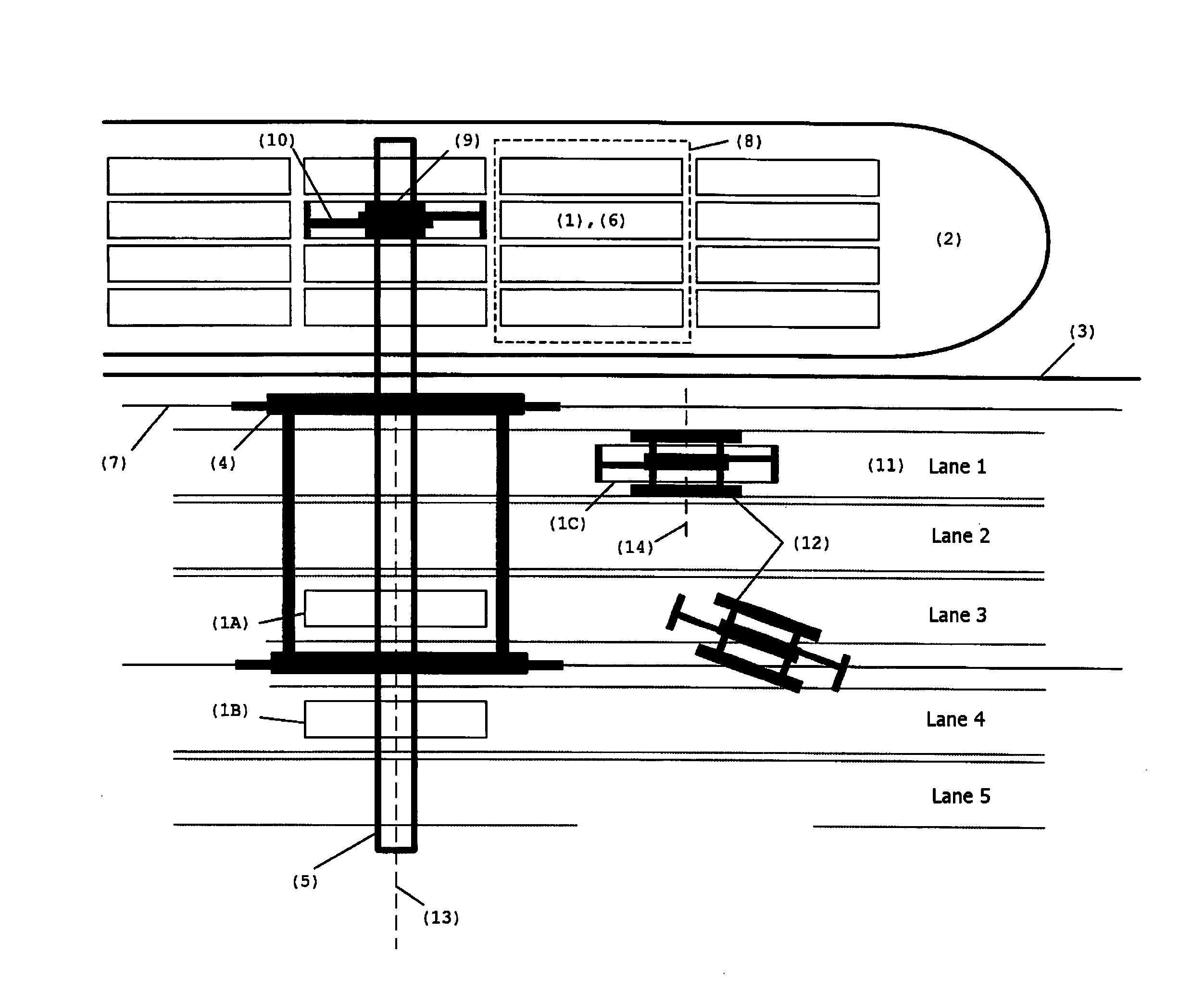
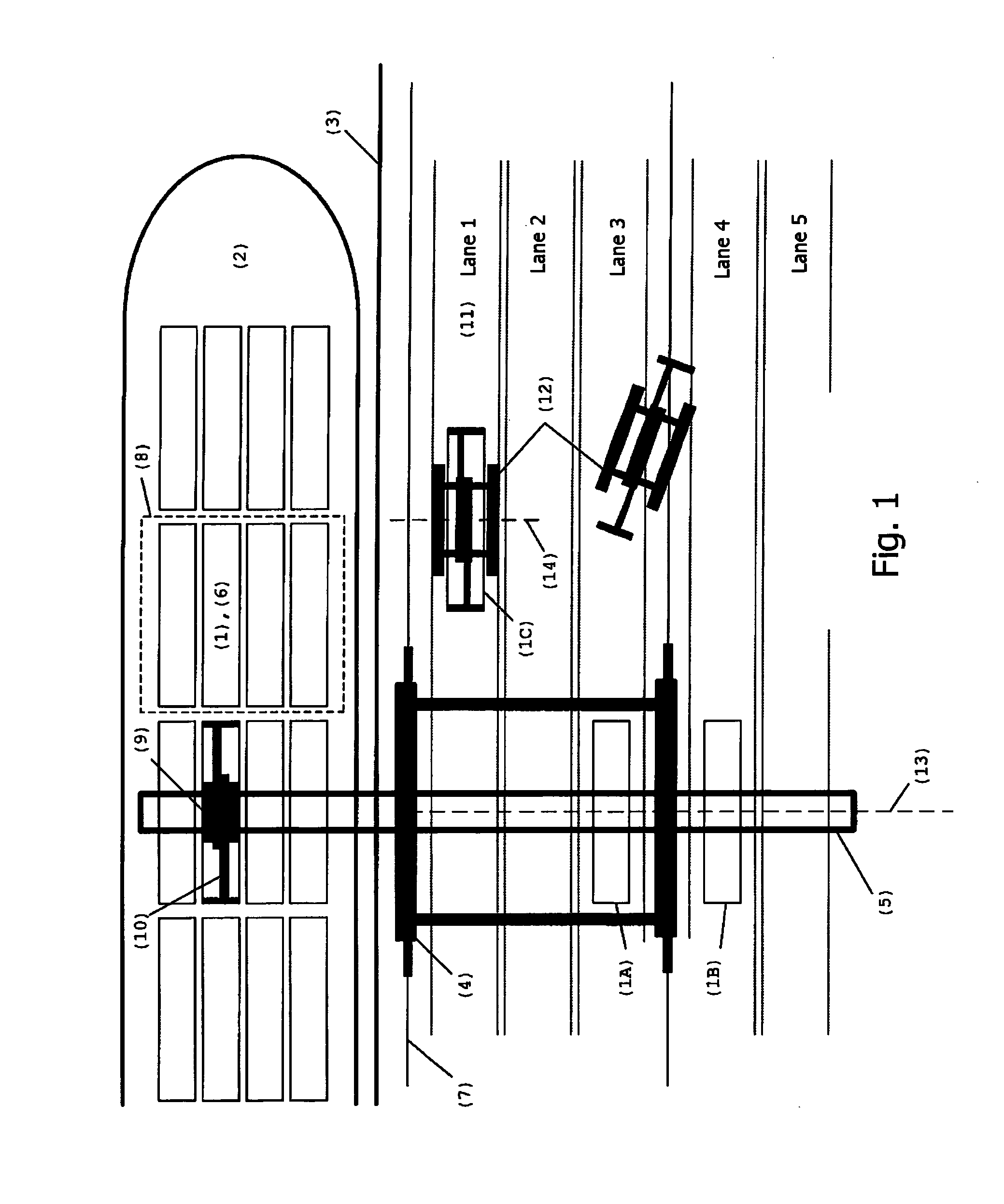
[0030]FIG. 1 shows unloading or loading of a container ship (2) by means of a quay crane (4);

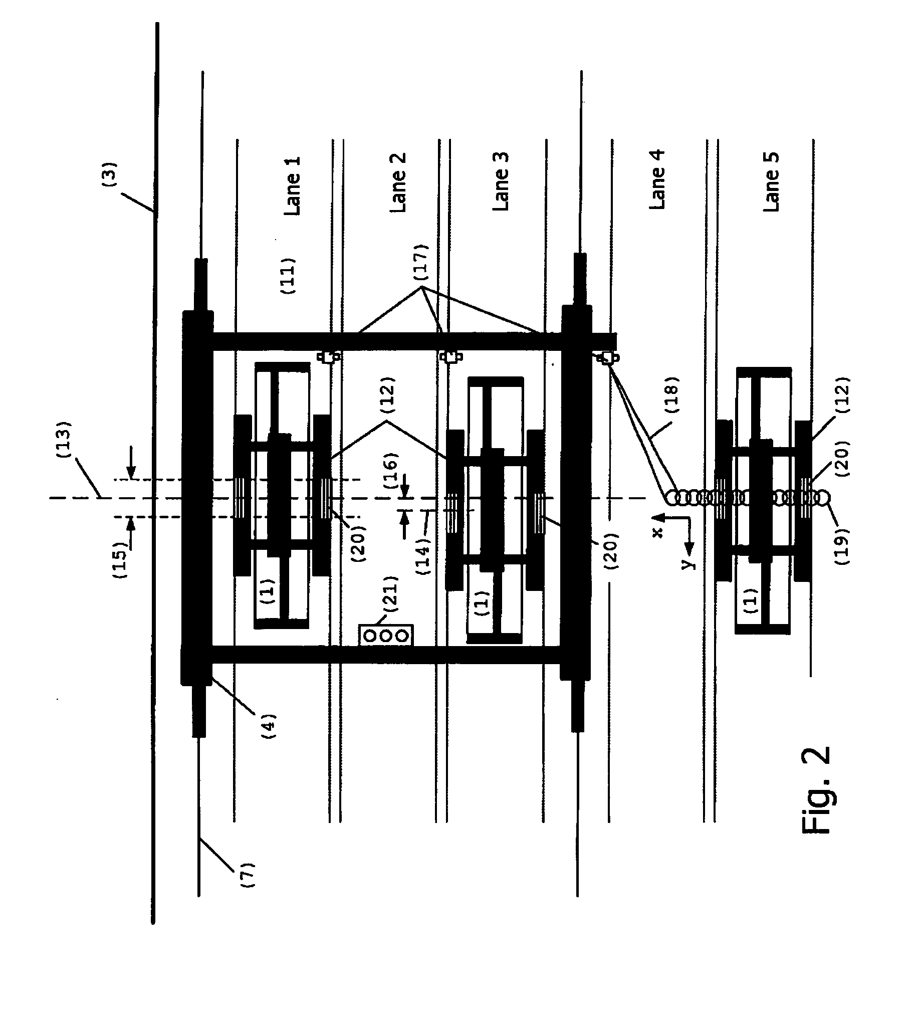
[0031]FIG. 2 shows lanes (11) underneath a quay crane (4) with container handling machines (12), for example a straddle carrier, bringing containers (1) therein;

[0032]FIG. 3 shows one way of implementing a reflector (20) of the invention;

[0033]FIG. 4 is a lateral view of lanes (11) underneath a quay crane (4) with container handling machines (12), for example a straddle carrier, bringing containers (1) therein;

[0034]FIG. 5 shows one possible method of implementing the invention;

[0035]FIG. 6 shows one possible algorithm for implementing the invention; and

[0036]FIG. 7 shows one way of im...


PUM


Abstract

The invention relates to a system capable of determining in which lane a container handling machine is present below a quay crane or the like crane and / or capable of determining the correct location of a container handling machine in its driving direction (y) with respect to a quay crane or the like crane as containers are delivered to the crane or containers are retrieved from the crane by the container handling machine. The crane is fitted with at least one scanning laser distance sensor or the like range finder, and the container handling machines are fitted with one or more reflectors whose height profile is used for the determination of a correct location and / or for the identification of a container handling machine and for the distinction thereof from other container handling machines.

Description

[0001]The invention relates to a system as set forth in the preamble of the appended claim 1 for the identification of a container handling machine and / or for determining the location of a container handling machine. Both alternatives apply the same new and inventive features as subsequently revealed.DESCRIPTION OF A PROBLEM TO BE ADDRESSED[0002]The operation of a typical container port shall now be explained to the extent necessary for understanding the invention in terms of its operation. Most of the international transports of goods proceed nowadays by way of containers (1). Containers are standard shape transport units, inside which the goods are packed for the duration of a transport. Containers come typically in three different sizes, either 20 feet, 40 feet or 45 feet in length. Containers arrive in and respectively depart from a container port carried either by a container ship (2), container trucks or container trains. A standard shape transport unit makes the handling of c...

Claims


Application Information

Patent Timeline
Patent Type & Authority Applications(United States)
IPC IPC(8): G01S17/88
CPCB66C13/46G01S17/88
Inventor RINTANEN, KARISAMPO, MIKKO
Owner KONECRANES GLOBAL
Why Eureka
Try Eureka