Robotic microscopy systems

Active Publication Date: 2006-11-21
THE J DAVID GLADSTONE INST A TESTAMENTARY TRUST ESTABLISHED UNDER THE WILL OF J DAVID GLADS
View PDF36 Cites 107 Cited by
  • Summary
  • Abstract
  • Description
  • Claims
  • Application Information

AI Technical Summary

Benefits of technology

[0005]The invention comprises a robotic microscope system and methods that allow high through-put analysis biological materials, particularly living cells, and allows precise return to and re-imaging of the same field

Problems solved by technology

Still, no available microscopy systems effectively provide for high throughput techniques for observation of living cells, with imaging of living cells carried out in a multi-well format.
Parti

Method used


Image

  • Robotic microscopy systems
  • Robotic microscopy systems
  • Robotic microscopy systems

Examples


example 1

Selection and Detection—Simultaneous Measurement of Multiple Variables

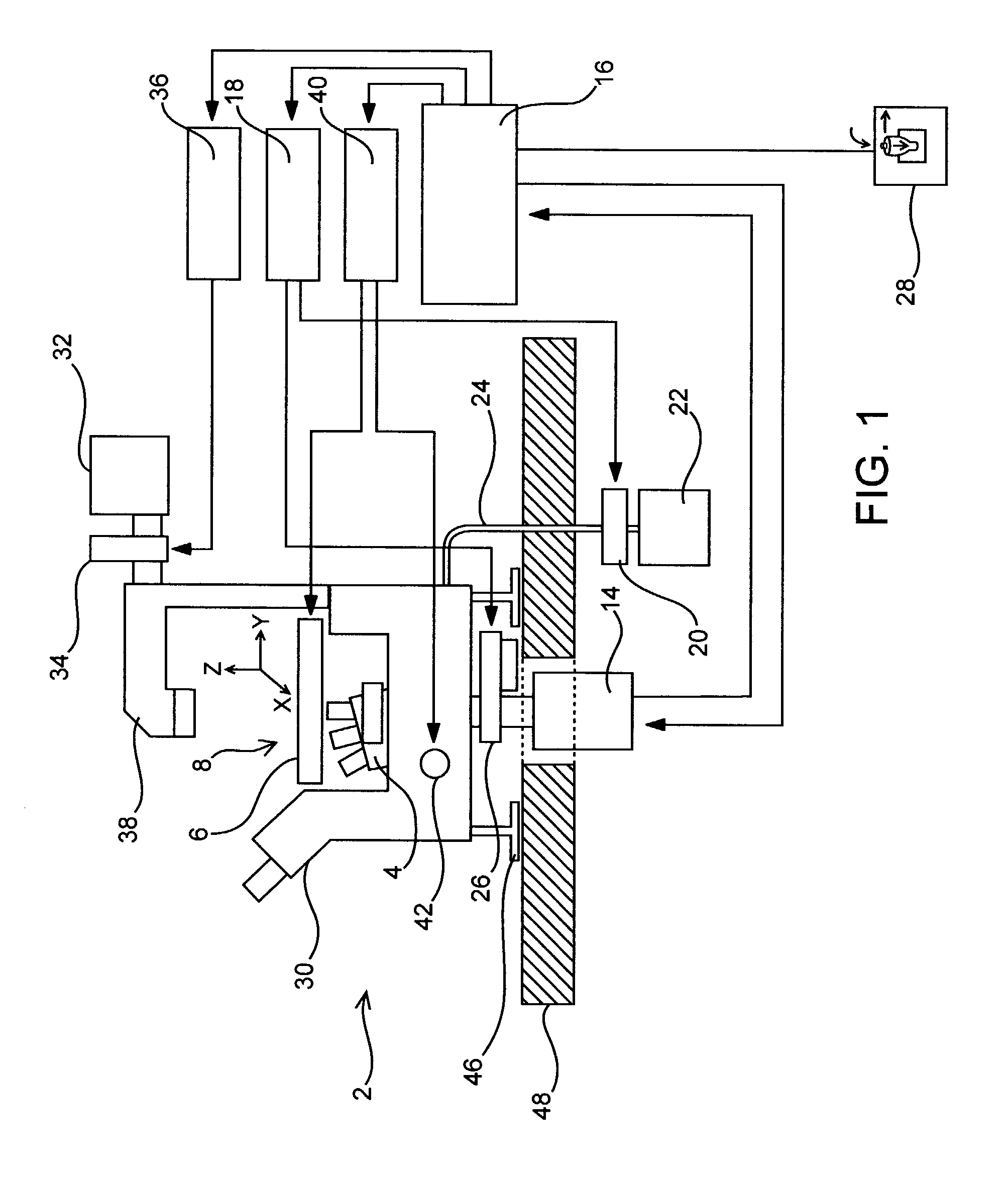
[0160]To maximize the amount of information collected in a single experiment, the total number of independent variables that can be simultaneously measured and then related to cell (e.g., neuronal) function is maximized. The wavelength and intensity of light are two properties that can be used to resolve independent variables using the present invention. To this end, fixed multi-band pass dichroic mirrors and 10-position excitation and emission filter wheels were used to examine fluorescent signals from selected portions of the spectrum. A computer controls the filter wheels to coordinate their movements during automated image acquisition. A 14-bit charge-coupled device (CCD) camera was used to resolve a wide range of signal intensities for a particular band-width of light. Finally, the camera used to capture images was placed at the basement port of the inverted microscope to minimize the complexity of the light ...

example 2

Automated Stage Movements and Focus with Low and High Numerical Aperture Objectives

[0162]To automate image acquisition, the microscope was equipped with computer-controlled motorized stage and focus. To find the focal plane, software moves the focus knob to sample images at different positions along the z-axis. The image analysis software measures each image's overall spatial frequency by performing a fast Fourier transform. The image with the highest spatial frequency determines the focal plane. The motorized stage was used to determine the number of stepper motor movements needed to move the stage one complete microscope field in the four cardinal directions using 4×, 10×, 20×, and 40× objectives. Programs were then constructed that sequentially focus the microscope, move the desired excitation and emission filter wheels into place, capture an image, and then move the microscope to an adjacent non-overlapping field and repeat the sequence. According to the type of tissue culture p...

example 3

Focusing for Different Wavelengths

[0173]Another problem became apparent during attempts to collect images of the same microscope field using different wavelengths of fluorescent light. Lenses refract different wavelengths of light by different amounts so the images formed from different wavelengths of emitted fluorescence were not focused exactly to the same point. The differences were small enough so that they were undetectable for low numerical objectives (e.g., 4×, N.A. 0.13). However, with increasing numerical aperture these differences could be resolved. Consequently, as the excitation and emission filters were changed, the objective had to be repositioned to keep images of the same microscope field sharply focused.

[0174]It was also discovered that the focal plane determined by automated focusing with transmitted light could be used as a reference to determine the position of the focal plane of fluorescence images. For a particular fluorophore, objective, excitation and emissio...


PUM


Abstract

The invention comprises a robotic microscope system and methods that allow high through-put analysis biological materials, particularly living cells, and allows precise return to and re-imaging of the same field (e.g., the same cell) that has been imaged earlier. This capability enables experiments and testing hypotheses that deal with causality over time intervals which are not possible with conventional microscopy methods.

Description

CROSS-REFERENCE TO RELATED APPLICATIONS[0001]Benefit to U.S. Provisional Patent Application 60 / 337,585, filed Dec. 5, 2001 and entitled “Robotic Microscopy System and Method” is claimed. The entirety of that application (including its written Specification and the attached Drawings which provide additional information about the systems and methods of the invention) are hereby incorporated by reference, even such portions as not presently set forth herein.BACKGROUND OF THE INVENTION[0002]Inverted microscope configurations and computer control for automatic focusing and microscope stage positioning have been used for imaging of biological samples, for example, U.S. Pat. No. 4,000,417 discloses a computer automated system for blood cell counts and blood cell morphology studies. The system provides automated x-y stage translation, auto-focusing, and an automated meander search pattern system for cell finding. The system also provides for memorization of x-y positions for re-insertion of...

Claims


Application Information

Patent Timeline
IPC IPC(8): G06K9/00G01N21/64G01N21/25G01N21/27G01N21/78G02B21/36
CPCG01N21/253G01N21/6452G01N21/6458G02B21/367
Inventor FINKBEINER, STEVEN M.
Owner THE J DAVID GLADSTONE INST A TESTAMENTARY TRUST ESTABLISHED UNDER THE WILL OF J DAVID GLADS
Why Eureka
Try Eureka