Radar system

a radar system and target detection technology, applied in the field of radar systems, can solve the problems of difficult detection of targets, distortion of modulation waveforms, oscillation characteristics of vcos, etc., and achieve the effects of easy and reliable and accurate detection of targets over a wider rang

Inactive Publication Date: 2007-02-22
MURATA MFG CO LTD
View PDF8 Cites 27 Cited by
  • Summary
  • Abstract
  • Description
  • Claims
  • Application Information

AI Technical Summary

Benefits of technology

[0013] Accordingly, it is an object of the present invention to provide a radar system capable of resolving a problem caused by any distortion in a modulation wave without complicating the system and increasing the cost of the system to easily detect a target with higher accuracy.
[0019] According to the embodiment of the present invention described in (1), multiple window functions having amplitudes (weights) that are differently attenuated from the center of the sampling period toward both sides are selectively applied as the window function that is applied to sampled data in yield of a discrete frequency spectrum. A window function having a sharper peak in the frequency spectrum due to the reflection signal from the target can be selected to produce the sharp peak in the frequency spectrum. Alternatively, a peak can be selected from the frequency spectra resulting from the application of the multiple window functions to use the sharp peak in the frequency spectrum. Accordingly, the radar system is not greatly affected by any distortion in the modulation waveform, thus achieving easy and accurate detection of the target. Specifically, the window function having an amplitude that is gently attenuated from the center of the sampling period toward both sides is applied in a lower frequency band in the frequency spectrum and the window function having an amplitude that is sharply attenuated from the center of the sampling period toward both sides is applied in a higher frequency band in the frequency spectrum in order to yield the frequency spectrum. Consequently, the sharp peak can be produced over a range from the lower frequency band to the higher frequency band in the frequency spectrum and, therefore, it is possible to realize reliable and accurate detection of the target over a wider range.
[0020] According to the embodiment of the present invention described in (2), the window function having an amplitude that is gently attenuated from the center of the sampling period toward both sides is applied when it is predicted that the peak appears in a lower frequency band in the frequency spectrum, and the window function having an amplitude that is sharply attenuated from the center of the sampling period toward both sides is applied when it is predicted that the peak appears in a higher frequency band in the frequency spectrum. Accordingly, a sharp peak can be produced regardless of the frequency in the frequency spectrum at which the peak appears, thus achieving reliable and accurate detection of the target over a wider range.
[0021] According to the embodiment of the present invention described in (3), the detection of the target by the target detecting means is repeated, and the window functions having amplitudes that are differently attenuated from the center of the sampling period toward both sides are selectively applied depending on the distance to the target, calculated in the last detection or a detection previous to the last detection. Accordingly, a sharp peak caused by the target can be produced in the frequency spectrum depending on the target to be detected and, therefore, it is possible to reliably track the target even with a signal having a low SN ratio.
[0022] According to the embodiment of the present invention described in (4), the window function having an amplitude that is gently attenuated from the center of the sampling period toward both sides is applied while the vehicle is driving at a lower speed, and the window function having an amplitude that is sharply attenuated from the center of the sampling period toward both sides is applied while the vehicle is driving at a higher speed. Accordingly, it is possible to accurately detect a distance to the target that is possibly located at close range with higher accuracy while the vehicle is driving at a lower speed and to reliably detect the target that is possibly located at far range while the vehicle is driving at a higher speed.
[0023] According to the embodiment of the present invention described in (5), the window function having an amplitude that is gently attenuated from the center of the sampling period toward both sides is applied in ranges having larger scanning angles with respect to the front of the vehicle and the window function having an amplitude that is sharply attenuated from the center of the sampling period toward both sides is applied in a range having a smaller scanning angle with respect to the front of the vehicle. Accordingly, it is possible to increase the detection accuracy of the target (another vehicle) at far range in the front of the vehicle and to increase the detection accuracy at close range in diagonal directions on the left and right sides of the front of the vehicle.

Problems solved by technology

However, the oscillation characteristics of the VCOs are liable to vary due to the temperature characteristics or due to aging to cause distortion in the modulation waveform.
The triangular modulation wave with any distortion does not provide a sharp peak in the frequency spectrum even if discrete Fourier transform is performed in a manner described below, thus making the detection of the target difficult or causing a significant error.
As a result, there are problems in that it becomes difficult to detect a target and that a distance cannot be detected with higher accuracy.
However, since the DA converter or the DSP (an arithmetic processor in the DSP) is required, the system undesirably becomes complicated and increases the cost of the system.
In addition, since it is necessary to calculate compensation values of individual VCOs or to measure the temperature characteristics of individual VCOs to perform the correction, there is a problem in that the measurement, adjustment, and setting works require a large amount of time and effort and increases the manufacturing cost.
Furthermore, since a feedback loop is not used in the correction, the correction can involve shifts due to aging.
Although the problem due to aging can be resolved if a feedback loop, such as a phase locked loop (PLL), is used in the correction, the circuit configuration becomes complicated and greatly increases the manufacturing cost.

Method used


Image

  • Radar system
  • Radar system
  • Radar system

Examples


first embodiment

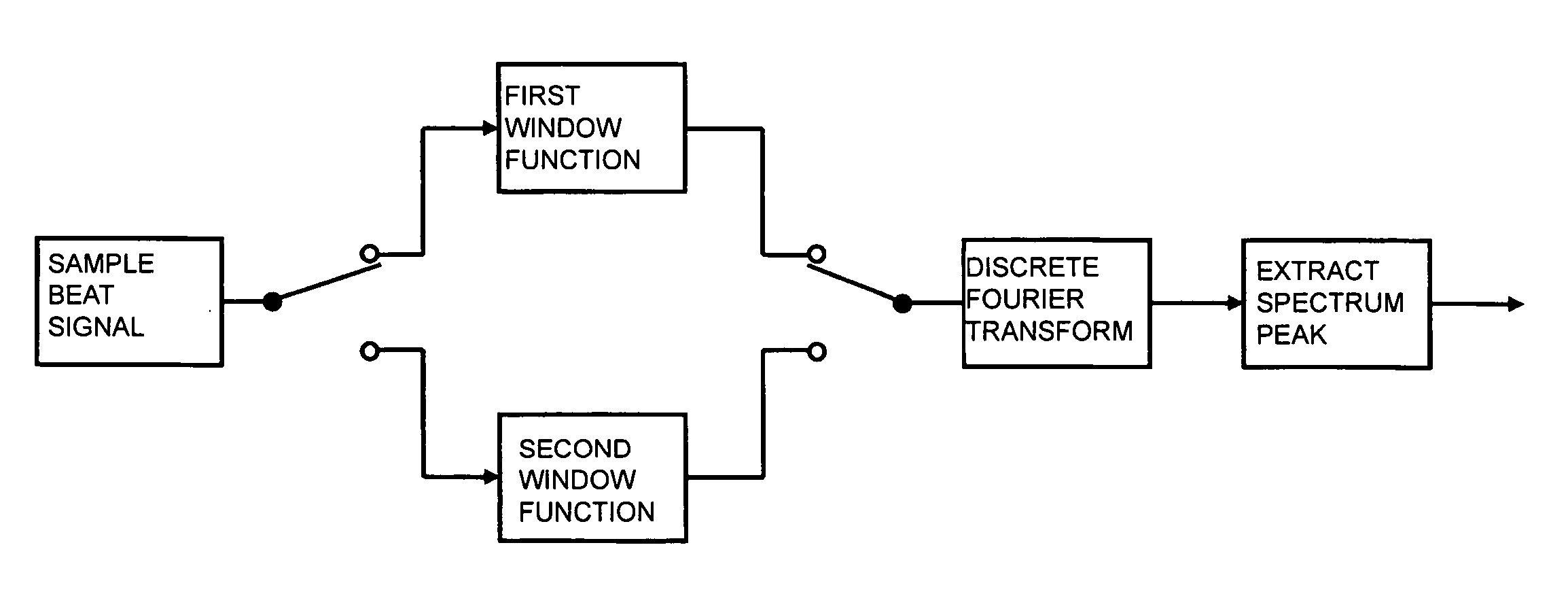
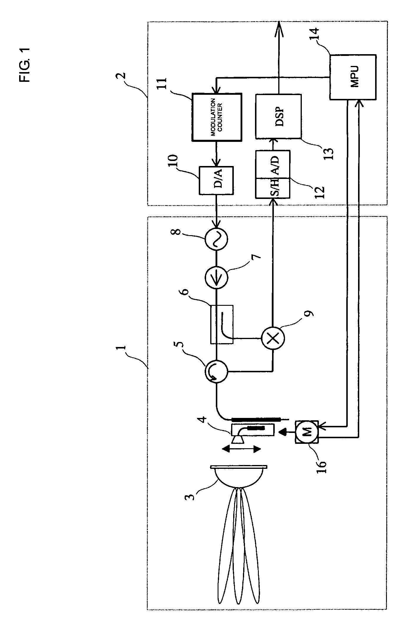
[0052]FIG. 3 is a block diagram showing a signal processing system in the DSP 13 shown in FIG. 1. beat signals are sampled, a first window function is applied to the sampled data sequence, and discrete Fourier transform is performed in a first frequency analysis. Similarly, a second window function is applied to the sampled data sequence and the discrete Fourier transform is performed in a second frequency analysis. Finally, a spectrum peak is extracted from the first and second frequency spectra.

[0053] The window function is applied to the sampled signals when the discrete frequency spectrum of the beat signal is to be yielded by the FFT or the like to suppress an influence of the discontinuity of the signal.

[0054]FIG. 4 includes graphs showing examples of the signal processing to which the window function is applied and the frequency spectra resulting from the signal processing. FIG. 4(A) shows the time waveform of a beat signal. A predetermined window function shown in FIG. 4(B...

second embodiment

[0072] The structure of a radar system will now be described with reference to FIG. 12.

[0073] According to the first embodiment, as shown in FIG. 3, beat signals are sampled during the sampling period to yield a predetermined number of pieces of data and the first and second frequency analyses are performed to the sampled data. In contrast, in the example shown in FIG. 12, the sampled data is decimated and the first frequency analysis is performed to the decimated data. Specifically, the first frequency analysis uses the pieces of sampled data of a number that is smaller than that of the pieces of sampled data used in the second frequency analysis.

[0074] As shown in FIGS. 10(A) and 10(B), since the frequency spectrum yielded when the first window function is applied uses a near range (lower frequency range), it is enough to sample a smaller number of pieces of sampled data. Accordingly, performing the frequency analysis to the decimated data allows the required processing power to...

third embodiment

[0075] A radar system will now be described with reference to FIG. 13.

[0076] Although the first and second frequency analyses are simultaneously performed in the first and second embodiments, the first and second frequency analyses may be performed in a time-shared manner. For example, as shown in FIG. 13, the application of the first window function to the data about the sampled beat signals to perform the discrete Fourier transform may be performed at a timing different from a timing when the second window function is applied to the data about the sampled beat signals to perform the discrete Fourier transform. In addition, the first or second window functions may be selectively applied depending on a required frequency band as long as the first window function is applied to a lower frequency range (near range) in the frequency spectrum and the second window function is applied to a higher frequency range (far range) therein.

[0077] In other words, the current location of each tar...


PUM


Abstract

A radar system in which a beat signal is generated by transmitting a transmission signal that is subjected to frequency modulation into a triangular wave and receiving a reflection signal from a target, the beat signal is sampled, and a window function is applied to yield a discrete frequency spectrum. When the window function is applied, a first window function having an amplitude that is gently attenuated from the center of the sampling period toward both sides thereof is applied in a lower frequency band in the frequency spectrum (at close range), and a second window function having an amplitude that is sharply attenuated from the center of the sampling period toward both sides thereof is applied in a higher frequency band in the frequency spectrum (at far range).

Description

CROSS REFERENCE TO RELATED APPLICATIONS [0001] The present application is a continuation of International Application No. PCT / JP2005 / 007976, filed Apr. 27, 2005, which claims priority to Japanese Patent Application No. JP2004-141504, filed May 11, 2004, the entire contents of each of these applications being incorporated herein by reference in their entirety.FIELD OF THE INVENTION [0002] The present invention relates to systems detecting targets by using radio waves. More particularly, the present invention relates to a radar system detecting a target on the basis of the frequency spectrum of a beat signal yielded from a transmission signal and a reception signal. BACKGROUND OF THE INVENTION [0003] FM-CW (frequency modulated continuous wave) radar systems using millimeter radio waves have been developed as in-vehicle radar systems. In the FM-CW radar systems, a radio wave is subjected to frequency modulation within a predetermined frequency range around a predetermined frequency and...

Claims


Application Information

Patent Timeline
Patent Type & Authority Applications(United States)
IPC IPC(8): G01S13/42G01S13/93G01S13/34G01S13/931
CPCG01S13/345G01S2013/9375G01S2007/356G01S13/426G01S13/931G01S2013/93271G01S7/356
Inventor NISHIMURA, TETSUISHII, TORU
Owner MURATA MFG CO LTD
Why Eureka
Try Eureka