In-vehicle power line communication system

a communication system and power line technology, applied in the direction of electric controllers, ignition automatic control, instruments, etc., can solve the problems of increased system weight, decreased vehicle mounting ability, increased system construction cost, etc., to reduce the cost of system construction and prevent noise generation

Active Publication Date: 2012-06-14
HONDA MOTOR CO LTD
View PDF23 Cites 24 Cited by
  • Summary
  • Abstract
  • Description
  • Claims
  • Application Information

AI Technical Summary

Benefits of technology

[0018]Accordingly, it is possible to reduce the cost of system construction without damaging marketability.
[0019]In the in-vehicle power line communication system according to (2), by including the choke coil upstream from the power line communication network, that is, between the pow...

Problems solved by technology

However, in the in-vehicle communication system according to the above-mentioned related art, since two transmission structures of the data bus structure and the supply line structure are necessary for information transmission between the in-vehicle components, there is a problem in that the cost of system construction increases, the system weight increases, and the vehicle-mounting ability decreases.
Moreover, by only connecting plural in-vehicle components through the use of the supply line structure in a vehicle, it is not possible to prevent noise generated from various in-vehicle components from being su...

Method used


Image

  • In-vehicle power line communication system
  • In-vehicle power line communication system
  • In-vehicle power line communication system

Examples


Embodiment Construction

[0022]Hereinafter, an in-vehicle power line communication system according to an embodiment of the invention will be described with reference to the accompanying drawings.

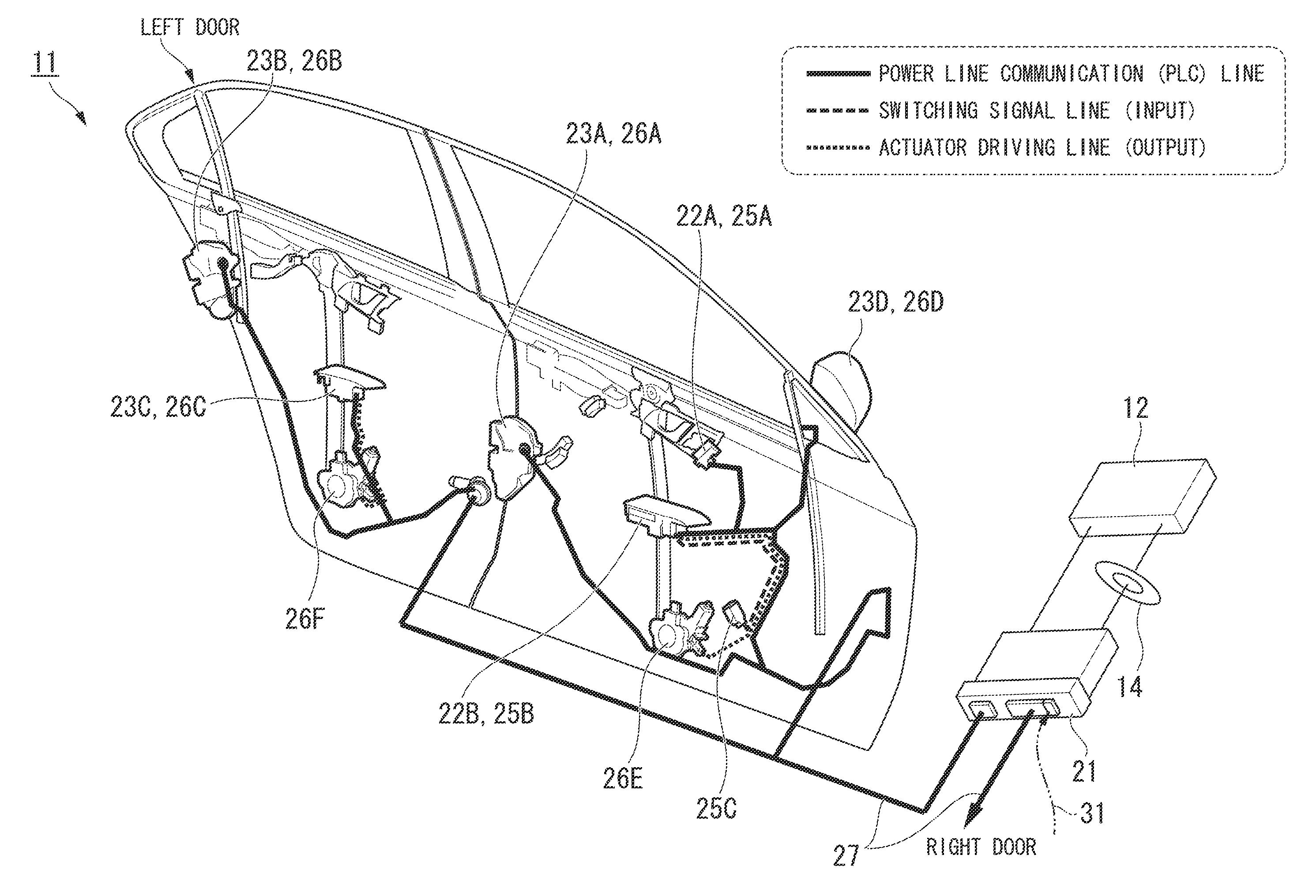
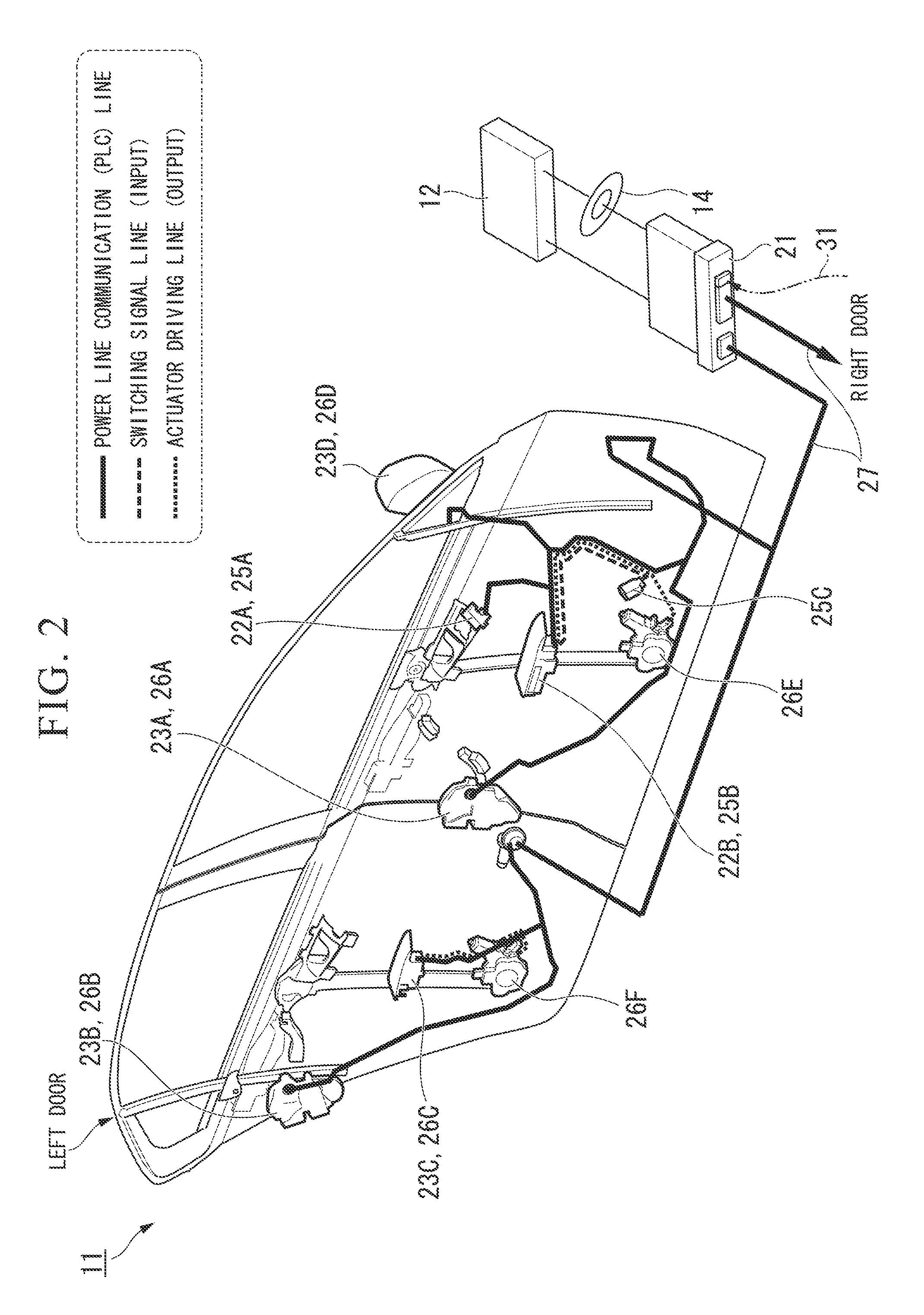
[0023]In the in-vehicle power line communication system 10 according to this embodiment, for example, as shown in FIG. 1, a power line communication network 11 and a battery 12 mounted on a vehicle are connected to each other via a first power line 13 and a choke coil 14 is installed in the first power line 13.

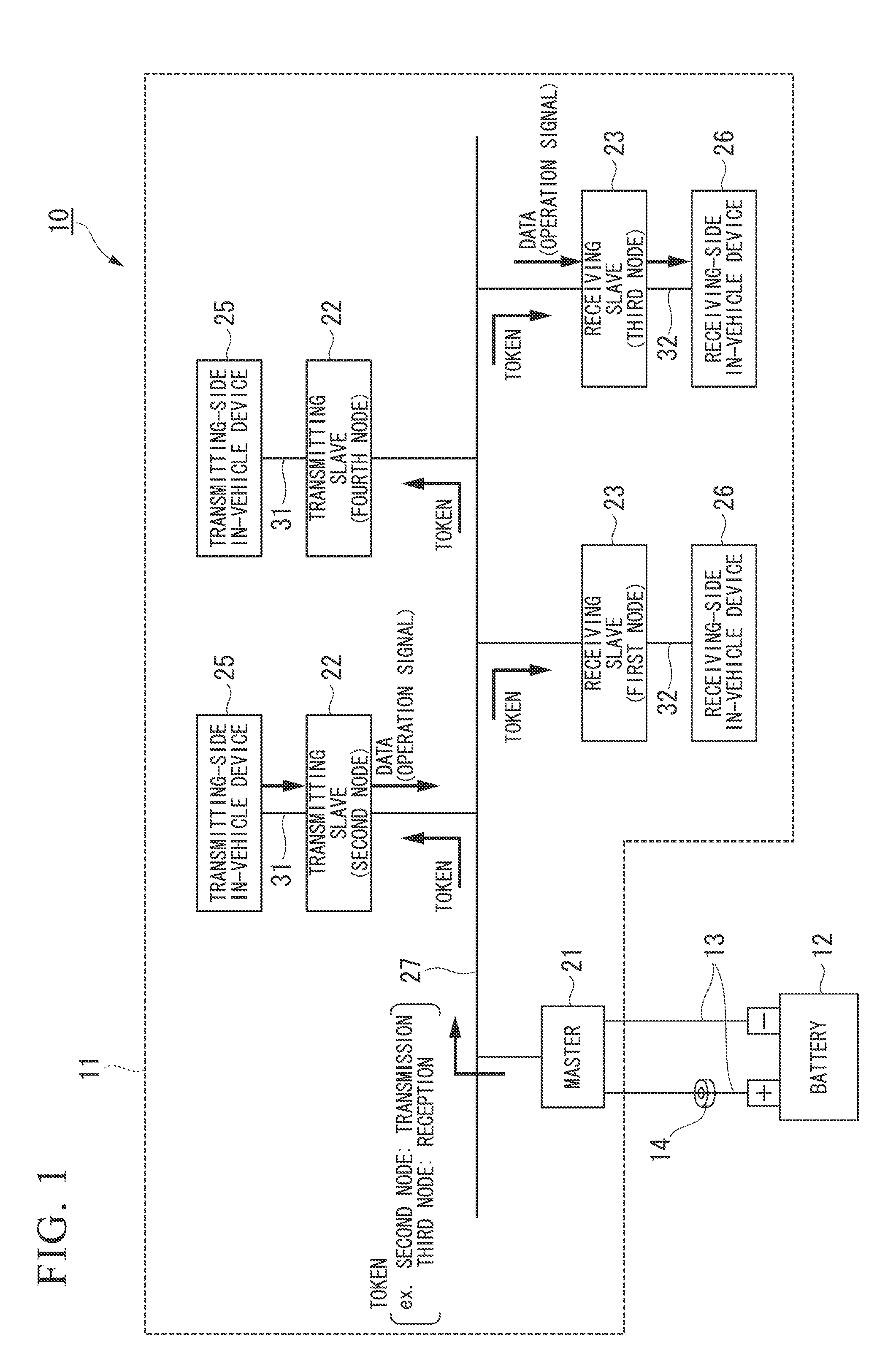
[0024]The power line communication network 11 includes, for example, a master power line communication node 21, plural (for example, two) transmitting slave power line communication nodes 22, plural (for example, two) receiving slave power line communication nodes 23, plural (for example, two) transmitting-side in-vehicle devices 25, plural (for example, two) receiving-side in-vehicle devices 26, and a second power line 27 connecting the communication nodes 21, 22, and 23.

[0025]The master power line communica...


PUM


Abstract

In an in-vehicle power line communication system in which a power line communication network and a battery are connected to each other via a first power line, the power line communication network includes a master power line communication node connected to the battery via the first power line, a second power line, slave power line communication nodes including at least a transmitting slave power line communication node and a receiving slave power line communication node, a transmitting-side in-vehicle device, and a receiving-side in-vehicle device. The master power line communication node and the slave power line communication nodes communicate with each other using a time-triggered communication protocol. The mutual communicating of the slave power line communication nodes are controlled by a token signal output from the master power line communication node. Only the master power line communication node and the slave power line communication nodes are connected to the second power line.

Description

BACKGROUND OF THE INVENTION[0001]1. Field of the Invention[0002]The present invention relates to an in-vehicle power line communication system.[0003]Priority is claimed on Japanese Patent Application No. 2010-278538, filed Dec. 14, 2010, the content of which is incorporated herein by reference.[0004]2. Description of Related Art[0005]For example, an in-vehicle communication system was known in the past, in which plural in-vehicle components are connected to each other through the use of a data bus structure capable of only transmitting information and a supply line structure capable of supplying power and transmitting information, information with low importance is transmitted through the use of only the data bus structure, and information with high importance is redundantly transmitted through the use of the data bus structure and the supply line structure (for example, see Japanese Patent No. 4331777).SUMMARY OF THE INVENTION[0006]However, in the in-vehicle communication system ac...

Claims


Application Information

Patent Timeline
IPC IPC(8): G08C19/16
CPCH04B2203/547H04B3/548
Inventor EGUCHI, TSUYOSHI
Owner HONDA MOTOR CO LTD
Why Eureka
Try Eureka