[0005]As a result, many researchers have proposed tethered sensor networks for monitoring structural performance over time, commonly termed
structural health monitoring (SHM). Using a few distributed sensors (e.g. accelerometers) installed within the civil infrastructure then coupled with automated
damage detection algorithms at the centralized data repository, a comprehensive SHM
system can be formed.
Structural health monitoring can objectively monitor long-term
structural reliability and serviceability. However, the high costs to install and maintain the extensive coaxial cables connecting sensors to the centralized data repository have warranted novel cost-effective methods for SHM. For example, the cost to install tethered sensors in tall buildings and long bridges can exceed thousands of dollars on a per channel basis. High
system costs result in low sensor densities in large-scale civil infrastructures; as a result, generally only global vibration characteristics are deduced from so few sensors. Nevertheless, the advent of tethered sensors for SHM has initiated the shift from schedule-based to performance-based monitoring.
[0008]According to the principles of the present teachings, a prototype thin film passive
wireless strain and pH sensor is provided for localized strain and
corrosion monitoring. Encoding of electromechanical and electrochemical sensing transduction mechanisms (i.e. strain and pH, respectively) within a thin
film structure is accomplished by adopting material fabrication techniques derived from the
nanotechnology domain.
Nanotechnology provides tools and materials such that, by manipulating material properties at the molecular scale, one can utilize a “bottom-up” design methodology to yield high performance sensors. In particular, single-walled carbon nanotubes (SWNTs) and a variety of
polyelectrolyte (PE) species combined with a layer-by-layer (LbL) fabrication technique can produce a homogeneous multilayer
thin film sensor of controlled morphology. When coupled with a coil antenna, the final multifunctional sensor
package is capable of wirelessly detecting strain and pH via characteristic frequency and bandwidth changes, respectively.
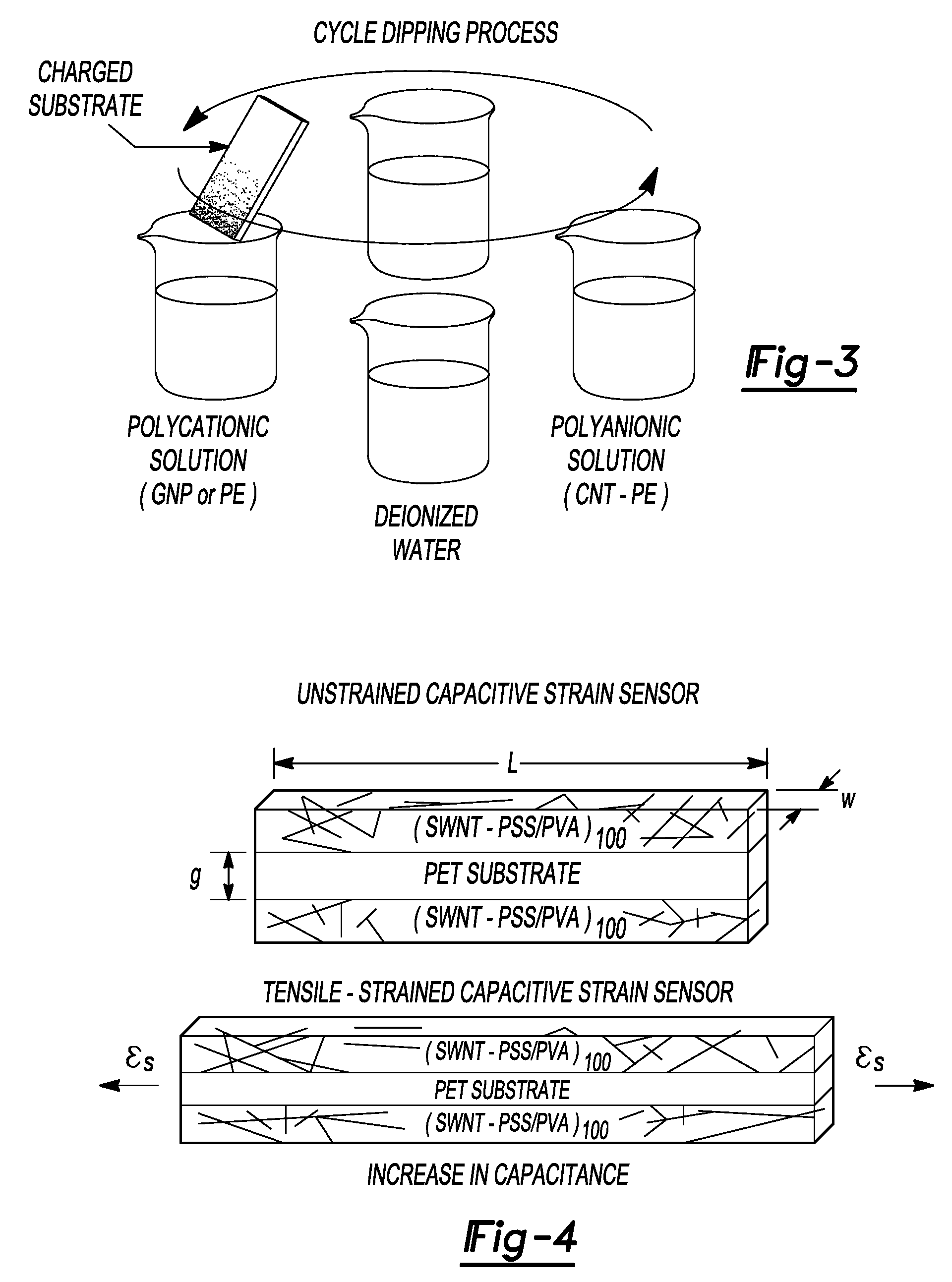
[0055]The first
monolayer in the LbL assembly process is deposited by dipping a clean, charged glass
microscope slide in a positively charged polycation solution (in this case, a PE solution such as poly(
vinyl alcohol) (PVA, Sigma) or
polyaniline (PANI, Aldrich)) for 5 min. Excessively large
particulates and loosely adsorbed PE species are rinsed off in 18 M_deionized water for 3 min, followed by a
drying step for 15 min to prevent cross-
contamination between the oppositely charged solutions. Using very fast magic-angle
spinning nuclear magnetic resonance (MAS NMR), Rodriguez et al has verified that the adsorbed polyelectrolytes remain deposited even after rinsing. The CNT
monolayer deposition is achieved by dipping the PE-coated substrate in a stable, negatively charged polyanionic CNT dispersion (CNTs from Carbon Nanotechnologies, Inc.) for 5 min, followed by the rinsing /
drying steps described above. Here, a 1.0 wt %
aqueous solution of poly(
sodium 4-
styrene-
sulfonate) (PSS, 1000 000 Mw, Aldrich) is employed to achieve a stable, negatively charged suspension of CNTs. This process completes one
full cycle of the LbL assembly to form one
bilayer of the CNT-PE thin film. Multilayer thin-film assembly is realized by repeating the aforementioned procedure to fabricate free-standing films of 50 and 100 bilayers of different compositions (table 1).TABLE 1Matrix of 20 unique films fabricated.0.25 mg ml−1 SWNT0.50 mg ml−1 SWNT0.80 mg ml−1 SWNTStrain sensingu-SWNT-PSS / PVAa50 and 100 bilayers50 and 100 bilayers50 and 100 bilayersp-SWNT-PSS / PVAb50 and 100 bilayers50 and 100 bilayers50 and 100 bilayersp-DWNT-PSS / PVAc50 and 100 bilayers50 and 100 bilayers50 and 100 bilayerspH sensingp-SWNT-PSS / PANId——50 and 100 bilayersaUnpurified SWNTs dispersed in 1.0 wt % wt PSS with 1.0 wt % PVA LbL counterpart.bPurified SWNTs dispersed in 1.0 wt % PSS with 1.0 wt % PVA LbL counterpart.cPurified DWNTs dispersed in 1.0 wt % PSS with 1.0 wt % PVA LbL counterpart.dPurified SWNTs dispersed in 1.0 wt % PSS with 1.0 wt % PANI LbL counterpart.According to the principles of the present teachings, an n-
bilayer composite thin film fabricated with oppositely
charged species X and Y will be denoted as (X / Y)n. Specifically, three different CNTs are used (unpurified SWNTs (u-SWNTs), purified SWNTs (p-SWNTs), and purified DWNTs (p-DWNTs)). Also, two different PE species, PVA and PANI, are employed in the thinfilm composites for strain and
corrosion sensing, respectively.
[0056]In order to fully harness the impressive electrical properties of CNTs and to transfer these properties to tangible length scales (i.e. LbL thin films), a stable suspension and dispersion of CNTs in an
aqueous solution is necessary. Currently, many researchers have undertaken covalent stabilization techniques to molecularly bind specific species to CNT surfaces for enhanced dispersion and functionality; however, a noncovalent approach via steric stabilization of CNTs in
polyelectrolyte solutions is selected for this study as this method preserves the mechanical and electrical properties of individual nanotubes. A high-molecular-weight poly(
sodium 4-
styrene-
sulfonate) (Mw ? 1000 000) polyanion solution is employed to facilitate dispersion of single- and double-walled carbon nanotubes. Dispersion is achieved through 180 min in an ultrasonication bath (135 W, 42 kHz) followed by 90 min of high-powered probe
sonication (3.178 mm tip, 500 W, 22.0 kHz). Adequate dispersion of CNTs is verified with scanning
electron microscopy (SEM), where FIG. 17 shows deposition of only individual and small
nanotube bundles with the
percolation threshold exceeded. While it has been found in preliminary studies that PSS facilitates dispersion of SWNTs, Moore et al validate a wide variety of
polymer dispersive agents for CNTs. A key finding they report is that higher-molecular-weight polymers (e.g. PSS) tend to suspend more SWNTs due to their longer polymeric chains and the size of their hydrophilic groups for enhanced steric stabilization. Nevertheless, a wide variety of polymers and surfactants has been shown to provide adequate dispersion of nanotubes in solution. Preliminary UV-vis studies of CNT-PE thin films fabricated with PSS and PVA indicate greater
absorbance than films fabricated with other polyelectrolytes (namely PDMA, PAH, among others). Measured UV-vis
absorbance correlates to the amount of CNT deposition, thereby suggesting efficient
nanotube deposition per LbL fabrication cycle when using PVA as the LbL
electrolyte counterpart to PSS.
[0068]In some embodiments, highly conductive thin films can be fabricated using the layer-by-layer self-assembly method. While carbon nanotubes exhibit near-ballistic transport-type electronic behavior, the deposition of other
polyelectrolyte species during LbL greatly reduces bulk film
conductivity, through the incorporation of metallic nanoparticles (e.g. gold) within a
polymer matrix. LbL films have been successfully fabricated with bulk
metal conductivity. Through the addition of carbon nanotubes and a variety of polyelectrolyte species, it is believed that conductive coil antennas with embedded sensing transduction mechanisms can be achieved in a single LbL assembly process.
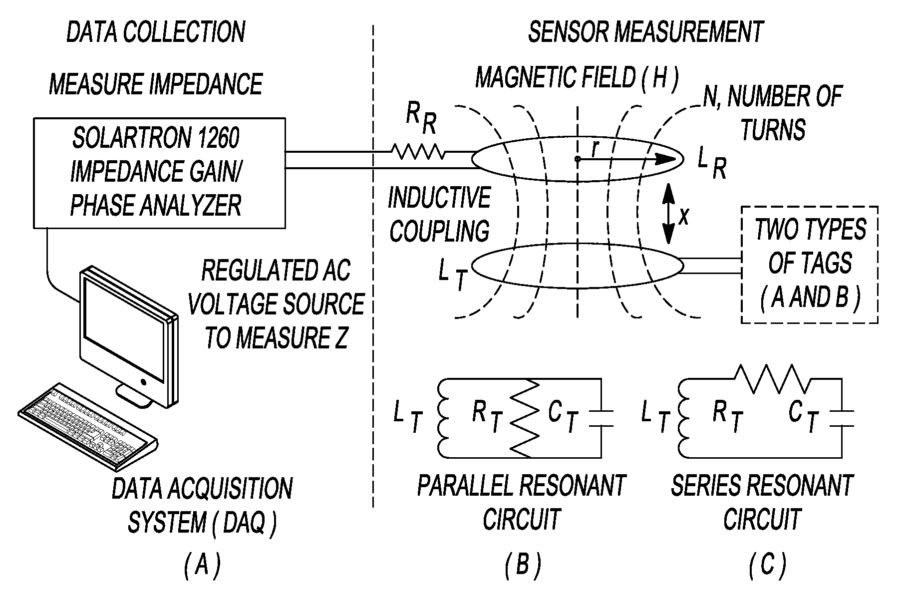
[0089]In some embodiments, fabrication of a multifunctional thin film passive
wireless sensor is accomplished by utilizing an adsorption-based layer-by-layer self-assembly technique to create an inductively coupled wireless thin film strain and pH sensor derived from an LbL assembled SWNT-gold
nanoparticle (GNP)
nanocomposite. Through the sequential dipping of a charged glass substrate in oppositely charged polycationic (GNPs in poly(
vinyl alcohol) (PVA) or
polyaniline (PANI)) and polyanionic solutions (SWNTs in
sodium dodecyl sulfate (SDS)), a homogeneous multilayer thin film of controlled morphology can be assembled. In some embodiments, (SWNT-SDS / PANI) resistive pH sensors and (SWNT-SDS / PVA) capacitive strain sensors are presented. Finally, GNPs are employed (FIG. 1) to enhance bulk
conductivity for wireless operations.

