
Lighting enclosure system

a technology of enclosure system and lighting enclosure, which is applied in the direction of fixed installation, transportation and packaging, lighting and heating equipment, etc., can solve the problems of time-consuming mounting of existing lighting enclosures and much valuable time spent on creating custom attachments, so as to avoid time-consuming and expensive custom fabrication.

Inactive Publication Date: 2011-04-07
PATTI ANTHONY G
View PDF5 Cites 42 Cited by
  • Summary
  • Abstract
  • Description
  • Claims
  • Application Information

AI Technical Summary

Benefits of technology

[0007]The primary object of the invention is to provide a lighting enclosure system that can accommodate a wide variety on installation conditions thereby avoiding time consuming and expensive custom fabrication of support members.
[0011]Yet another object of the invention is to provide a lighting enclosure system that allows the user to attach the lighting enclosure to hanging threaded posts.
[0012]Still yet another object of the invention is to provide a lighting enclosure system that allows the user to attach one lighting enclosure to another in an end to end fashion.

Problems solved by technology

Existing lighting enclosures can be time consuming to mount because the conditions of mounting within a given ceiling or wall or floor tend to vary.
Therefore, much valuable time is spent on creating custom attachment methods to fasten the lighting enclosure to the existing support structures found in the ceiling, wall or floor.

Method used


Image

  • Lighting enclosure system
  • Lighting enclosure system
  • Lighting enclosure system

Examples


Embodiment Construction

[0026]Detailed descriptions of the preferred embodiment are provided herein. It is to be understood, however, that the present invention may be embodied in various forms. Therefore, specific details disclosed herein are not to be interpreted as limiting, but rather as a basis for the claims and as a representative basis for teaching one skilled in the art to employ the present invention in virtually any appropriately detailed system, structure or manner.

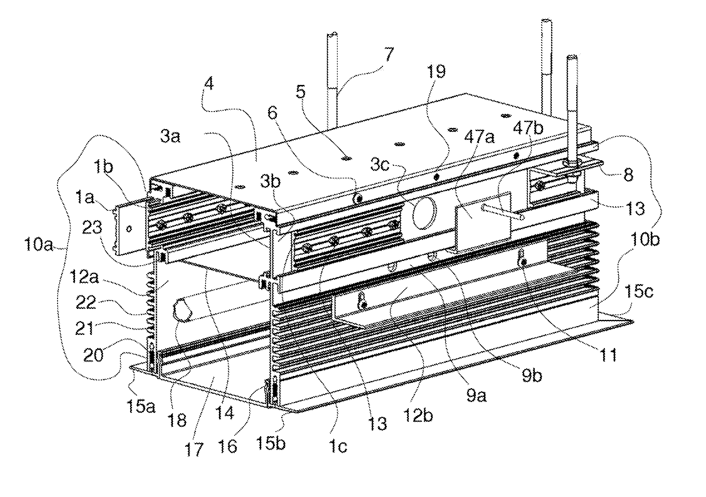
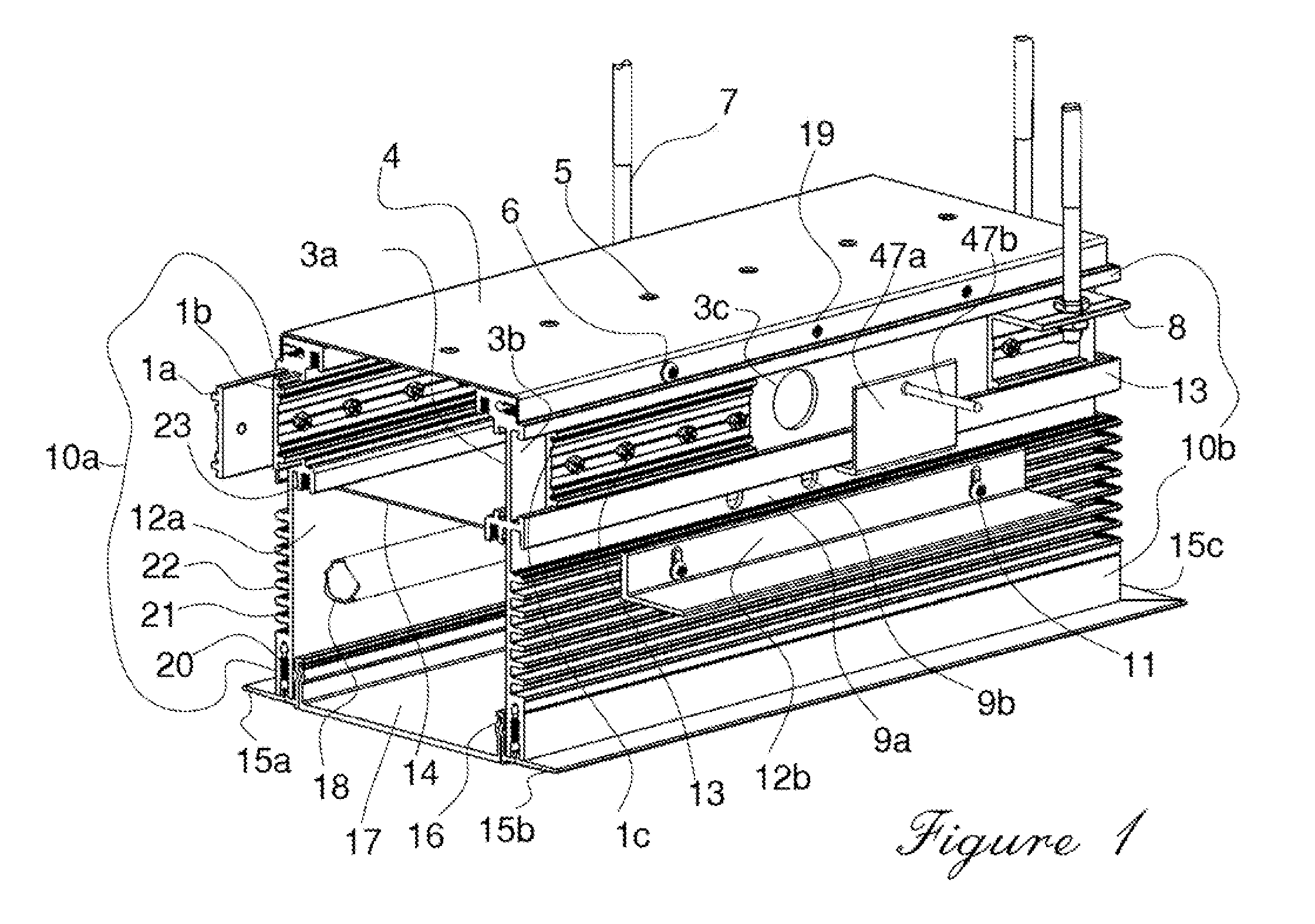
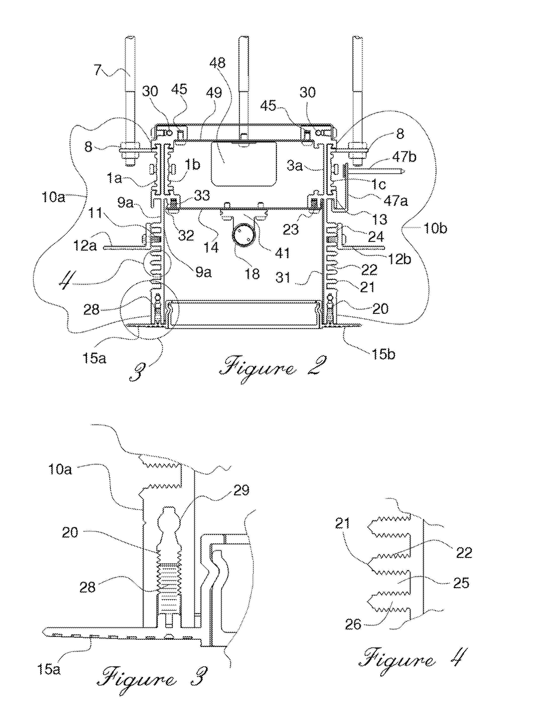
[0027]FIGS. 1 and 2 illustrate the first main or commercial embodiment of the present invention initially consisting of, but is not limited to, an enclosure or housing, that consists of a built-up assembly of multiple components designed with many functionally novel and mechanically unique properties: Uniquely extruded left and right side wall panels 10a and 10b, when used in a combinations with other such panels cut in matching or opposing lengths, allow for the initial foundations of robustly constructed enclosures or housings that...


PUM


Abstract

A lighting enclosure system with a right side extruded metal panel, a left side extruded metal panel, a top cover, a lamp holding panel, a light diffuser panel and a variety of flange members that allow the user to hang the lighting enclosure in a variety of conditions including suspended ceilings, sheet rock ceilings and walls. The right and left side metal brackets including a plurality of horizontally disposed, equally spaced outwardly projecting ribs, each the rib having a plurality of equally spaced, horizontally disposed screw thread retaining ridges that allow the user to attach the flange members in any desired location. Additional side brackets can attach one enclosure system with another in a linear fashion.

Description

CROSS REFERENCE TO RELATED APPLICATIONS[0001]This application is based on provisional application Ser. No. 61 / 278,574, filed on Oct. 7, 2009.STATEMENT REGARDING FEDERALLY SPONSORED RESEARCH OR DEVELOPMENT[0002]Not ApplicableDESCRIPTION OF ATTACHED APPENDIX[0003]Not ApplicableBACKGROUND OF THE INVENTION[0004]This invention relates generally to the field of lighting enclosures and more specifically to a lighting enclosure system for suspended ceilings that allows for a variety of mounting techniques.[0005]Lighting enclosures, meant to be hidden within the confines of a suspended ceiling and a true ceiling have become commonplace for use in offices, workplaces and some homes. Sometimes lighting enclosures are also hidden behind walls or under floors. Existing lighting enclosures can be time consuming to mount because the conditions of mounting within a given ceiling or wall or floor tend to vary. Therefore, much valuable time is spent on creating custom attachment methods to fasten the...

Claims


Application Information

Patent Timeline
Patent Type & Authority Applications(United States)
IPC IPC(8): F21V15/01
CPCF21S8/026F21Y2103/00F21V15/013
Inventor PATTI, ANTHONY G.
Owner PATTI ANTHONY G
Learn More