
Screwdriver with dual headed axial shaft

Inactive Publication Date: 2011-04-14
PALMISANO DOUGLAS
View PDF4 Cites 15 Cited by
  • Summary
  • Abstract
  • Description
  • Claims
  • Application Information

AI Technical Summary

Benefits of technology

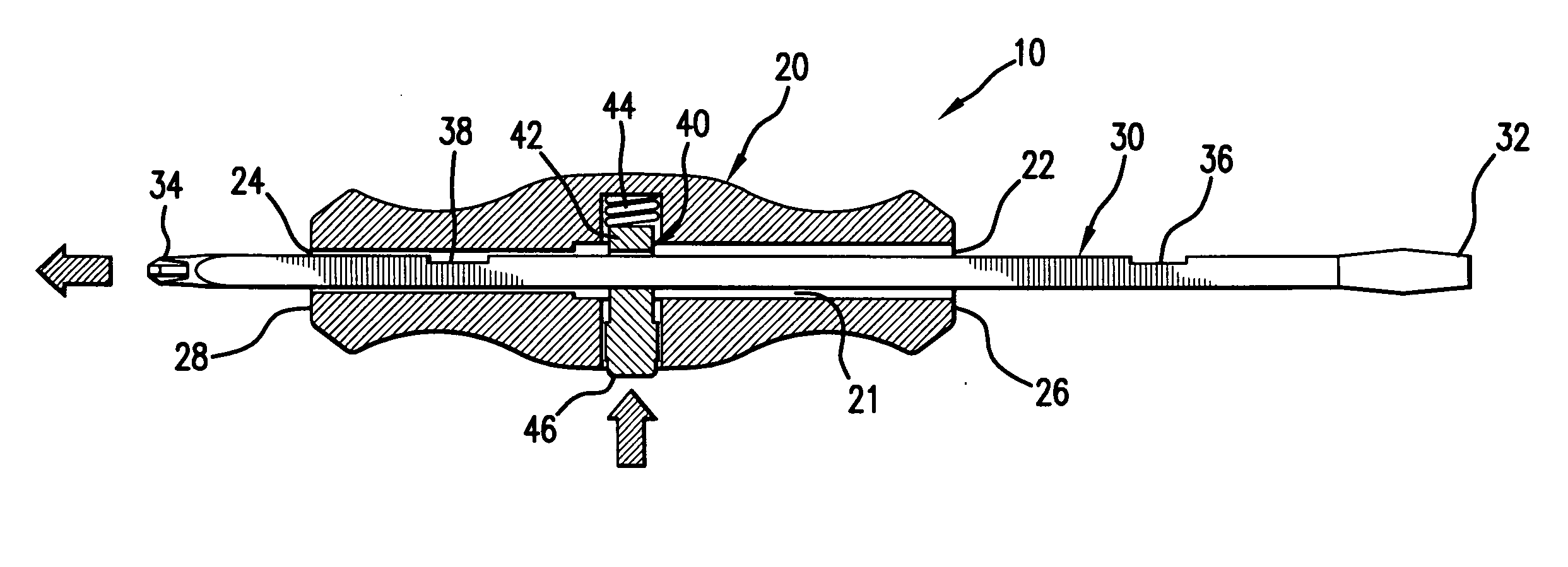
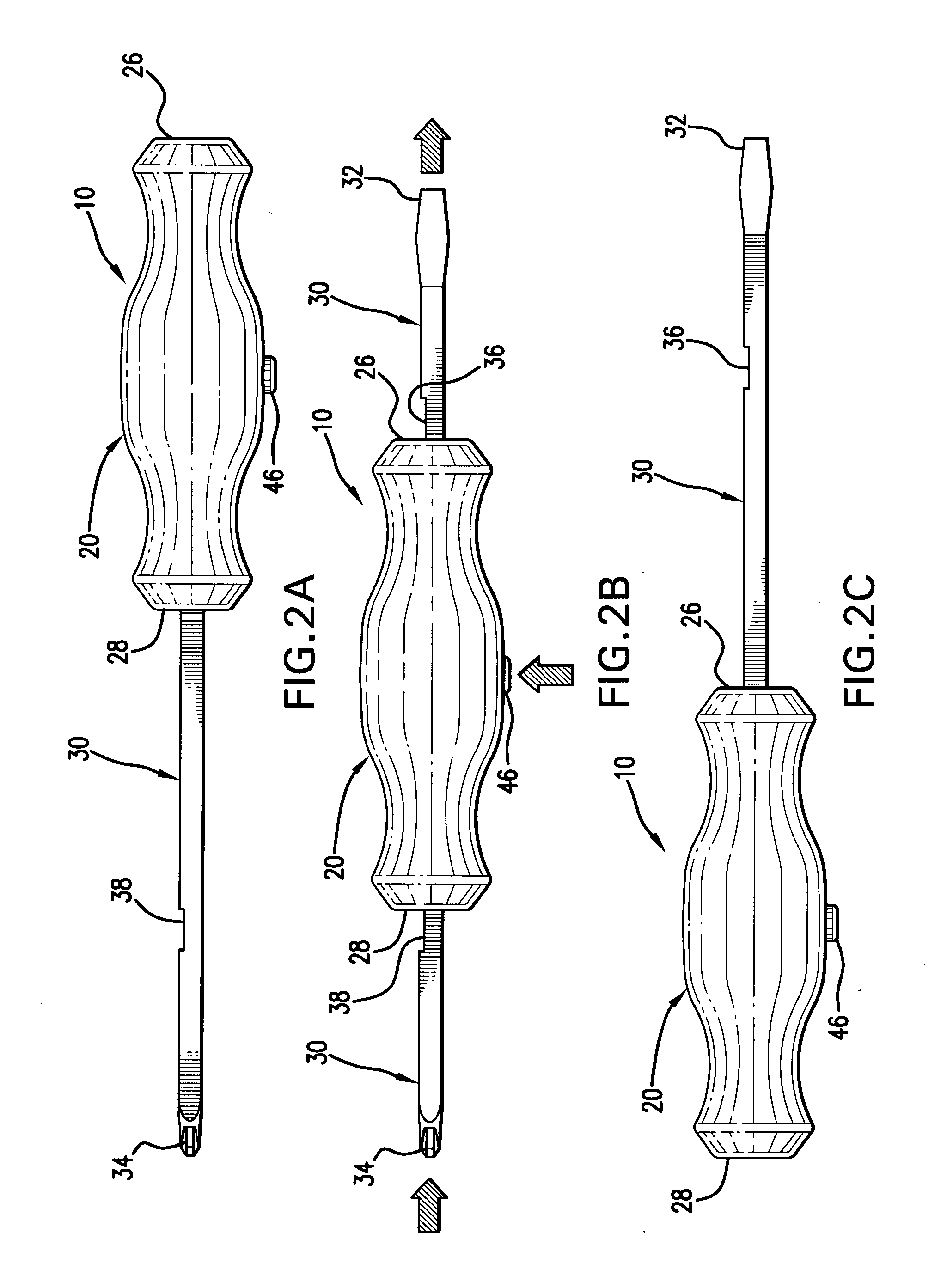
[0008]The present invention is directed to a screwdriver that allows the user to easily alternate between the use of two different screwdriver heads. The present invention includes an axial shaft member having two screwdriver heads located at opposite distal ends of the axial shaft member. The shaft member is sized to slide through an elongate channel that extends longitudinally through the screwdriver handle. The elongate channel is sized and configured to receive the shaft member with very little clearance, thereby allowing sliding movement of the shaft member through the handle without excess play or wobble. A locking mechanism on the screwdriver handle serves to lock the axial shaft member within the screwdriver handle, thereby safely exposing one of the two screwdriver heads at a time during use. A user can then release the locking mechanism and slide the axial shaft member within the screwdriver handle, exposing the second screwdriver head at the opposite end of the axial shaft member. The shaft member is then locked into place by the automatically engaging locking mechanism.

Problems solved by technology

As a wide range of screw sizes and contours are required for various manufacturing purposes, a complete tool set often includes a number of uniquely sized individual screwdrivers, which can require a large amount of storage space.
Given the wide range of different screws, however, a large amount of space is still required to house a complete set of replaceable screwdriver heads.
Such a screwdriver device, however, often requires awkward fumbling of multiple screwdriver bits in order to alternate between different sizes and contours.
The design of such a device, however, makes it difficult for a user to apply torque to a screw located in a narrow space, as the user is unable to rotate the device due to the presence of the second axial shaft.

Method used


Image

  • Screwdriver with dual headed axial shaft
  • Screwdriver with dual headed axial shaft
  • Screwdriver with dual headed axial shaft

Examples


Embodiment Construction

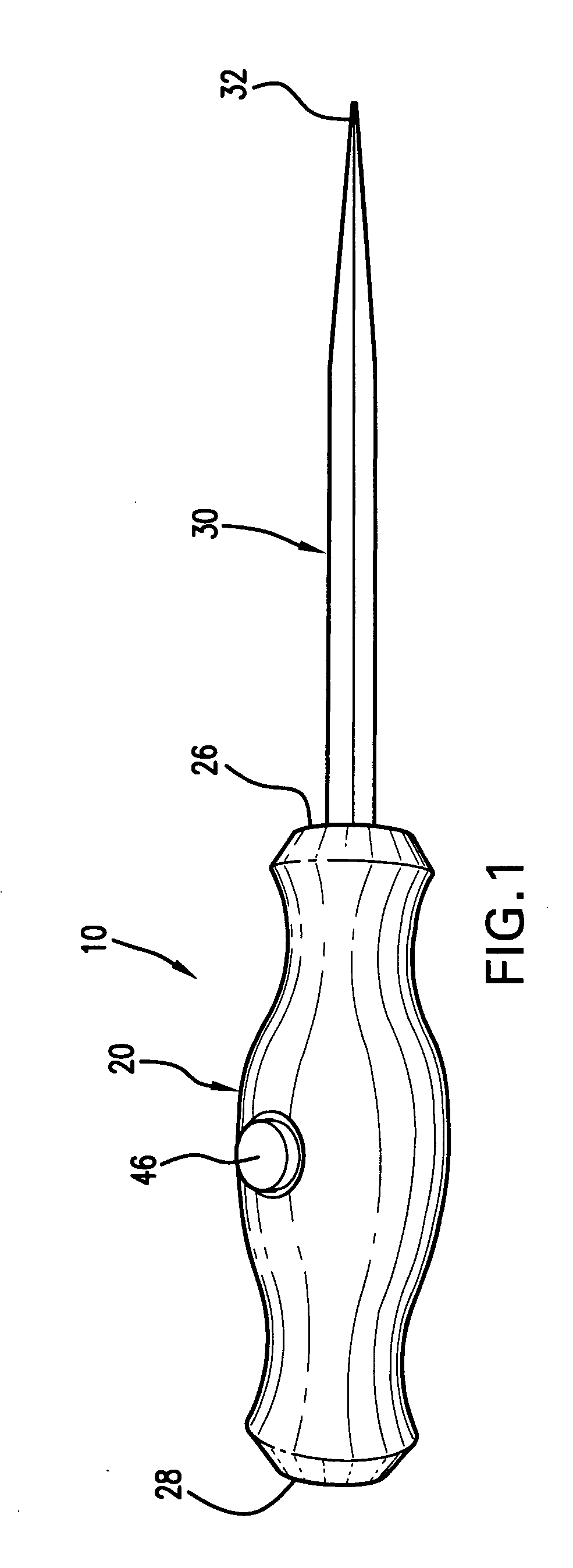
[0014]Referring to the several views of the drawings, the screwdriver with dual headed axial shaft is shown according to the several embodiments of the invention and is generally indicated as 10.

[0015]In each of the embodiments of the invention, the screwdriver 10 includes a handle 20 and an axial shaft member 30. Referring to FIGS. 1 and 4A-4B, the handle 20 is ergonomically shaped to be held within a user's hand and includes an elongate channel 21 extending throughout the length of the handle 20 between openings 22 and 24 at opposite ends 26, 28 of the handle 20. An axial shaft member 30 is sized to snuggly slide within the elongate channel 21 of the handle 20. The axial shaft member 30 includes a first distal end 32 and a second distal end 34, both of which include a particularly sized and contoured tool head. Recessed notches 36 and 38 are included along the length of the axial shaft member 30 engage with a locking member in order to lock the axial shaft member 30 into place pri...


PUM


Abstract

A screwdriver with a dual headed axial shaft allows for easy alternation between two screwdriver heads while maintaining the traditional screwdriver design. An axial shaft member having two screwdriver heads located at opposite distal ends of the axial shaft member is sized to snuggly slide through a longitudinal channel extending between opposite ends of the screwdriver handle. A locking mechanism on the screwdriver handle serves to lock the axial shaft member within the screwdriver handle, thereby safely exposing one of the two screwdriver heads at a time. A user can then release the locking mechanism and slide the axial shaft member within the screwdriver handle, exposing the second screwdriver head at the opposite end of the axial shaft member. The shaft member is then locked into place by the automatically engaging locking mechanism.

Description

BACKGROUND OF THE INVENTION[0001]This nonprovisional patent application is based on provisional patent application Ser. No. 61 / 278,885 filed on Oct. 14, 2009.FIELD OF THE INVENTION[0002]The present invention relates to a handheld mechanical tool and, more particularly, to a screwdriver device having a handle and an accompanying axial shaft member with opposing screwdriver heads located at the distal ends of the axial shaft member, and wherein the shaft member slides within the handle to allow for easy alternation between the differing screwdriver heads.DISCUSSION OF THE RELATED ART[0003]A screwdriver is a tool having an axial shaft with an affixed head that is used to engage and drive screws inwards with the application of torque, which the user creates by rotating the screwdriver. Typical manual screwdrivers include a cylindrical handle with an axial shaft protruding outwards from the handle. The axial shaft includes a head, which is formed into one of a variety of contours sized t...

Claims


Application Information

Patent Timeline
IPC IPC(8): B25B15/00B25B23/16
CPCB25B23/0042B25B15/02
Inventor PALMISANO, DOUGLAS
Owner PALMISANO DOUGLAS
Learn More