Mobile chair stop system

a technology for stopping systems and mobile chairs, applied in the field of mobile chairs, can solve the problems of user loss of balance, user injury, and inability to move the chair, and achieve the effect of convenient alternatement and optimal convenien

Inactive Publication Date: 2010-02-18
MONGELLUZZO MICHAEL ROBERT +1
View PDF4 Cites 5 Cited by
  • Summary
  • Abstract
  • Description
  • Claims
  • Application Information

AI Technical Summary

Benefits of technology

[0010]The present invention generally relates to chair stop systems, and, more particularly, to a chair stop device and mechanism incorporated into a mobile chair for enabling a stable, non-mobile state to be achieved as desired with optimal convenience, and to enable users to easily alternate between a mobile state and a non-mobile state in a single chair.

Problems solved by technology

However, there are some situations in which chair mobility is undesirable, and even dangerous to the user.
For instance, if someone needs to stand on the chair for any reason, e.g., to change a light bulb, a mobile chair is unstable and may roll while the user is standing, causing the user to lose balance and fall.

Method used


Image

  • Mobile chair stop system
  • Mobile chair stop system
  • Mobile chair stop system

Examples


first embodiment

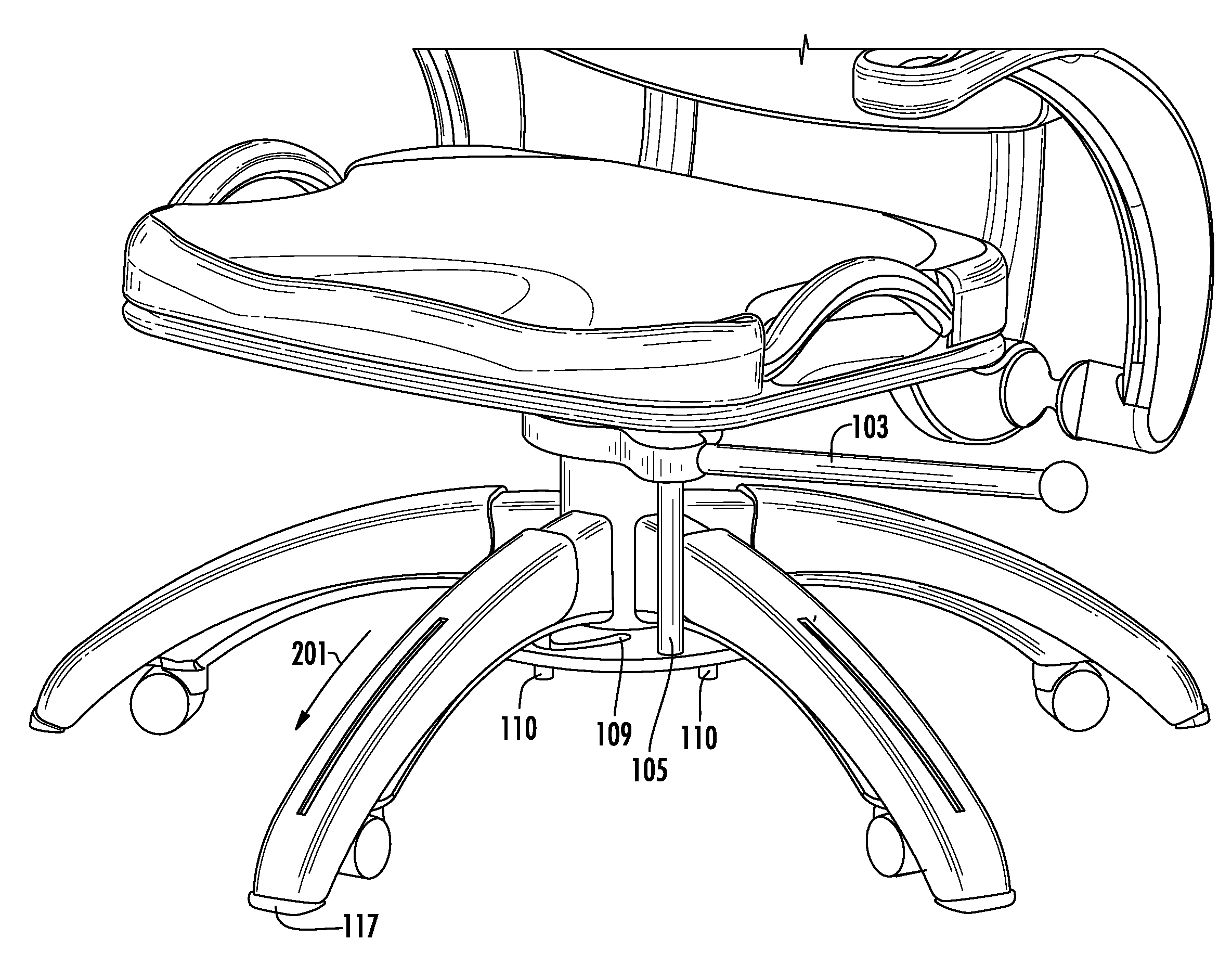
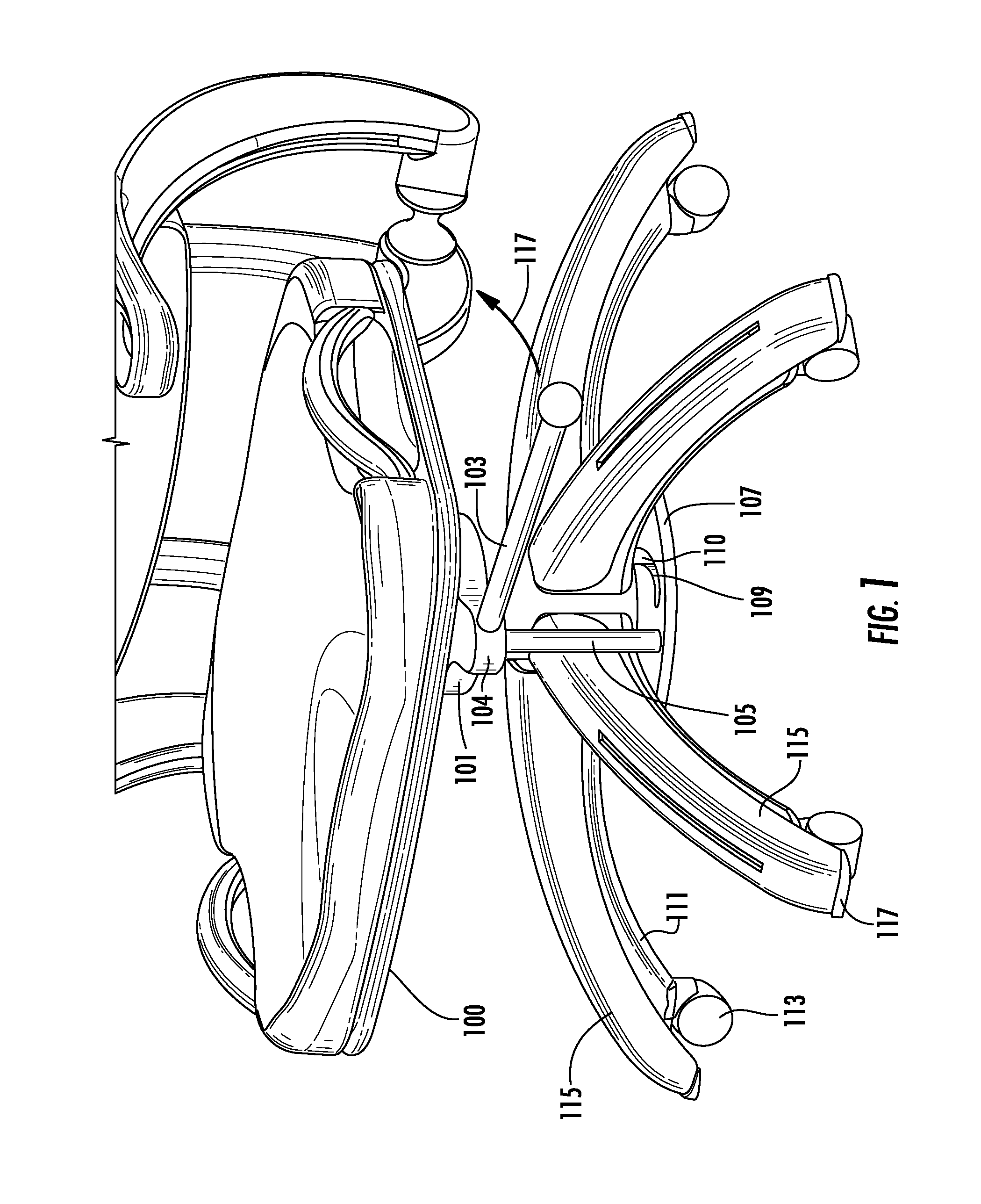
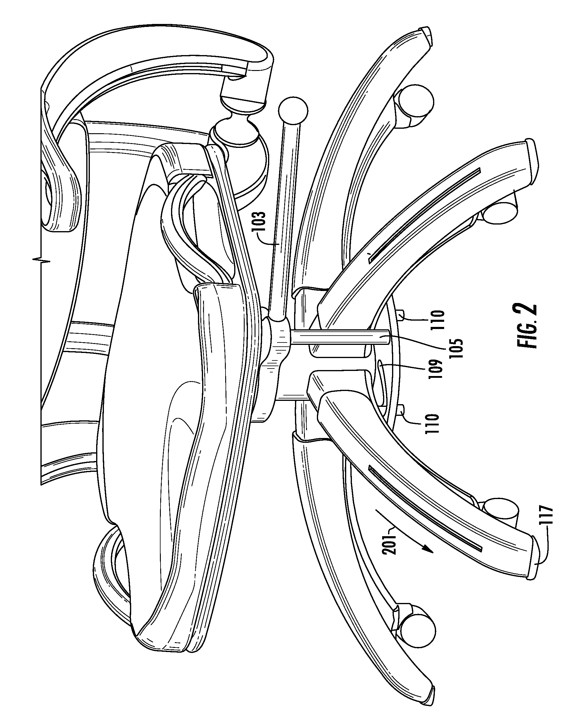
[0044]Referring now to the Figures, FIGS. 1-6 are exemplary views of a mobile chair stop system in mobile and stationary positions according to the present invention. FIGS. 1, 3 and 5 depict a chair in a mobile state, whereas FIGS. 2, 4 and 6 depict a chair in a non-mobile state.

[0045]In this exemplary embodiment, a mobile chair stop system is comprised of a cam member 101 having an aperture 102 adapted to allow the cam member 101 to be rotatably installed onto a chair support column 301. The cam member 101 may be comprised, e.g., of a disk-shaped object having, e.g., a circular aperture and a protruding arm 104 to which is attached a lever 103 adapted to extend from the cam member 101 in a sideways or horizontal direction.

[0046]The protruding arm 104 may comprise an elongate, curved (e.g., U-shaped) protrusion (although the protrusion may comprise any shape / size) and includes a rod 105 attached thereon at a first end and extending in a downwards vertical direction. The rod 105 may ...

second embodiment

[0057]FIGS. 7-12 are exemplary views of a mobile chair stop system in mobile and stationary positions according to the present invention. This embodiment depicts an exemplary “cylinder push system” for enabling the mobile and stationary positions. FIGS. 7, 9 and 11 depict a chair in a mobile state, whereas FIGS. 8, 10 and 12 depict a chair in a non-mobile state.

[0058]In this exemplary embodiment, a mobile chair stop system is comprised of a cylinder member 701 having an aperture 703 adapted to allow the cylinder member 701 to be slidably installed onto a chair support column 801. The cylinder member 701 is adapted to be slidable along the chair support column 801, and includes a plurality of cylinder attachment points 702 which permit jointed connection of chair stops 115. For example, such jointed connection may be achieved via provision of a center arm 707 having a first end pivotally connected to a cylinder attachment point 702, and a second end pivotally coupled to a chair stop ...

third embodiment

[0063]FIGS. 13-18 are exemplary views of a mobile chair stop system in mobile and stationary positions according to the present invention. This embodiment depicts an exemplary “crank system” for enabling the mobile and stationary positions, via rotation to translation forces. FIGS. 13, 15 and 17 depict a chair in a mobile state, whereas FIGS. 14, 16 and 18 depict a chair in a non-mobile or stationary state.

[0064]In this exemplary embodiment, a mobile chair stop system is comprised of a disk member 1303 having an aperture adapted to allow the disk member 1303 to be rotatably installed onto a chair support column 1305. The disk member 1303 includes a plurality of attachment points 1307 which permit movable connection of chair stops 115. For example, such movable connection may be achieved via provision of a pivot arm 1311 having a first end pivotally connected to the disk attachment point 1307, and a second end pivotally coupled to a chair stop attachment point 1309. The pivot arm 131...


PUM


Abstract

A stop system for a mobile chair having wheels is provided including a plurality of shroud members configured for covering each radial chair leg of the mobile chair. Each shroud member is movable in a first direction to enable a mobile state of the chair and in a second direction to enable a stationary state of the chair.

Description

BACKGROUND OF THE INVENTION[0001]1. Technical Field of the Invention[0002]The present invention generally relates to mobile chairs, and, more particularly, to a mobile chair stop mechanism for enabling a mobile chair to be switched between a mobile state and an immobile state when desired.[0003]2. Description of Related Art[0004]There exists today a wide range of mobile chairs, for example, task chairs and office / desk chairs which are adapted to be mobile via swivel casters, wheels, etc. In a typical configuration, a mobile chair is constructed having a seat mounted on a center post which connects to a multi-point mobile base, such as a five leg base having a swivel wheel connected at each leg end for contact with the ground.[0005]Mobility in a chair if often desirable in work situations in which the user must alter their position or location within a space, such as when multitasking between different workstations, adjusting to different locations / work distances at a desk, etc. Chai...

Claims


Application Information

Patent Timeline
Patent Type & Authority Applications(United States)
IPC IPC(8): B60B33/06A47C3/00B60T1/14A47C7/00
CPCA47C7/004A47C7/006B60B33/0039Y10T16/193B60B33/0057B60B33/0068B60B33/0089B60B33/0049
Inventor MONGELLUZZO, MICHAEL ROBERTMONGELLUZZO, RON
Owner MONGELLUZZO MICHAEL ROBERT
Why Eureka
Try Eureka