[0016]Further, according to the invention, a
signal encoding an image of the eye to be tracked is received at the graphics card. Because a number of preliminary
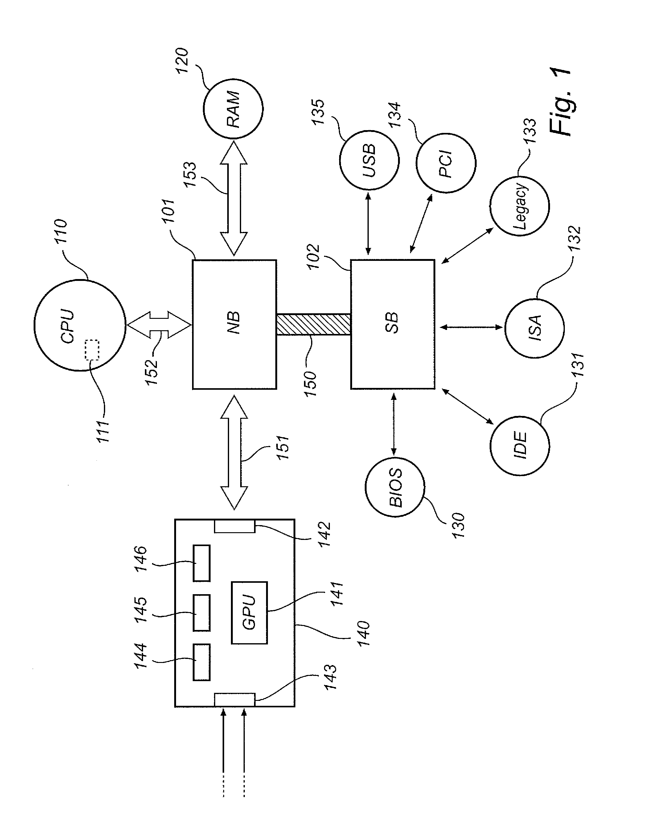
processing steps can thus be performed by the graphics card, the amount of data reaching the CPU can be considerably decreased by filtering out irrelevant image segments, pre-
processing the image data, extracting coordinates of image features and the like. Additionally, the fact that the
image signal is received at the graphics card, where it is processed, shortens the path of the input data flow, which would otherwise be transmitted over the
USB interface, the internal
bus and the graphics port or over some other chain of connected
motherboard devices. This efficient routing of the input data flow constitutes another
advantage of the invention.
[0017]In a second aspect of the invention, there is provided a computer-program product for carrying out the above method. In a third and fourth aspect of the invention, there are provided a gaze
tracking system and a personal computer system (this term is to be understood as indicated above) in which such gaze
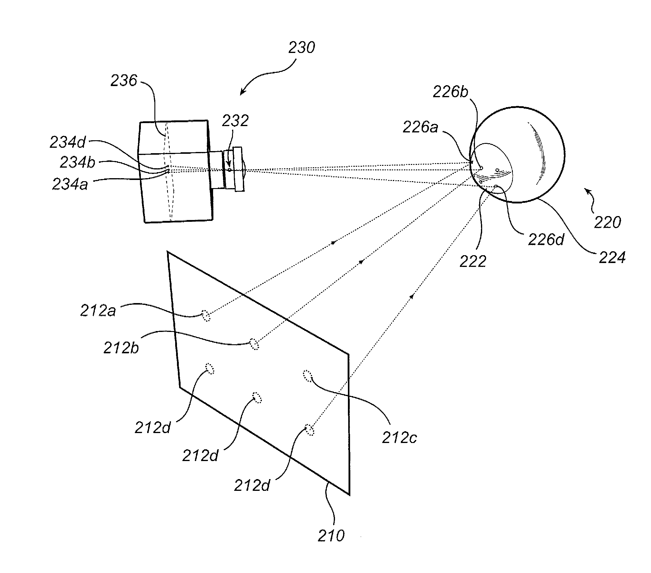
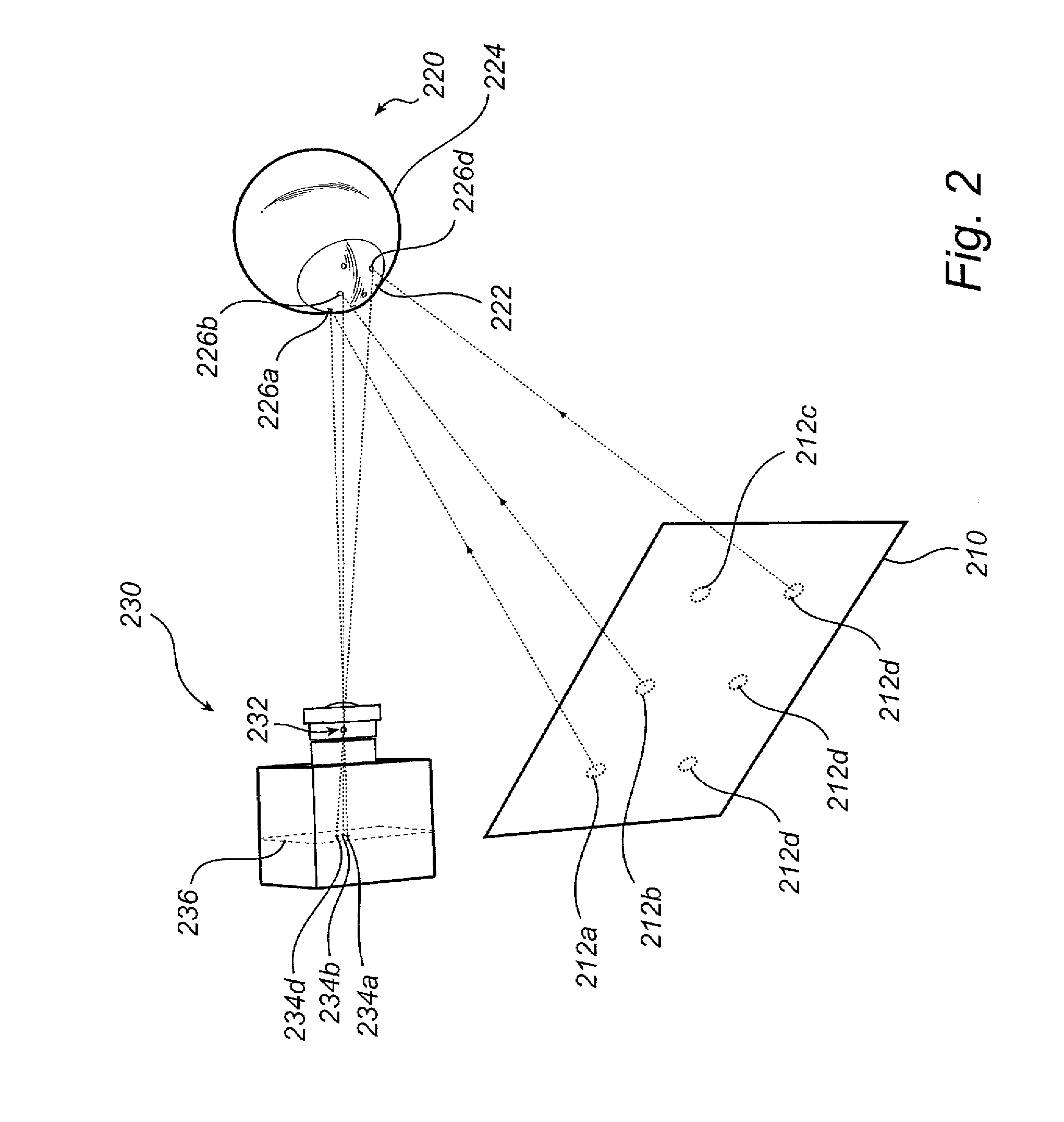
tracking system is integrated. The gaze tracking system comprises a visual display, a camera, a graphics card, and a gaze-point determining module. Here, the gaze-point determining module, which may be a
software module having authority to allocate resources within the system, is operable to cause the system to function in accordance with the method set forth above. A fifth aspect of the invention relates to use of a graphics card for carrying out certain tasks in connection with gaze tracking of an eye watching a visual display.
[0018]In one embodiment of the present invention, the graphics card extracts one or more image features in the corneo-scleral reflection of the screen pattern. The graphics card then deduces the corresponding positions of the one or more image features in the screen pattern from the display signal, which is provided to the visual display by the graphics card itself. The coordinates of the image features before and after reflection in the
cornea are used to determine a position of the eye. As an alternative, the display signal can be taken as starting point and regions of the screen pattern—with deformation, mirroring etc. taken into account—can be searched for in the reflection. In some embodiments, also the orientation of the eye is deduced from these coordinates.
[0019]In another embodiment, the eye is illuminated by at least one reference illuminator adapted to emit invisible light for producing a glint, a small, distinct luminous reflection on the corneo-scleral surface of the eye. The position of the glint, which is deduced from the image of the eye, is used for determining the gaze point of the eye. Wavelengths in the
infrared (IR) and near-
infrared (NIR) ranges are suitable for producing glints. Coaxial or non-coaxial illuminators, respectively for producing bright-
pupil and dark-
pupil eye images, may be applied, as considered appropriate. The reference illuminators may be integrated in the visual display or arranged thereon in a detachable fashion. Advantageously, the reference illuminators are light-emitting diodes (LEDs) provided in fittings having hooks, clips, suction cups or similar means for securing them to the visual display. As an alternative, the reference illuminators may be provided behind the display screen and aligned with suitable partial apertures provided therein, as described in EP 09 157106.
[0020]In a further embodiment, the image of the eye is received using an imaging device which is synchronised with the visual display. If the visual display responds to the display signal in real time, i.e., by plotting the image with zero or no time
delay, then the display signal can be used as a trigger to the imaging device. As an alternative, a dedicated trigger signal can be provided to both devices. Synchronisation is beneficial to the
image quality because
aliasing-related artefacts can be avoided by sampling the display image at the same frequency as it is updated. Among such artefacts are time oscillations of the (average) image intensity and steady or moving patterns of light and dark horizontal stripes. In particular, synchronisation between the imaging device and the visual display can be used for interlacing a distinctive reference pattern with the regular screen pattern. Advantageously, the regular screen pattern to be perceived by the human viewer occupies the largest part of a cycle while the reference pattern is displayed in a short time slot, invisibly to a
human eye. The reference pattern may contain image features that can be extracted easily or may be devised to facilitate measurements of the geometric deformation inflicted by the reflection. In particular, the reference pattern may include invisible light, such as
NIR light, emitted by the visual display or by reference illuminators.
[0021]In an alternative embodiment, the imaging device is instead synchronised with at least one reference illuminator. Hence, as a first option, the illumination by he reference illuminator(s) can be provided in a well-defined time slot, thereby enabling energy-economical operation of the reference illuminator. As a second option, a high degree of contrast can be achieved by subtracting the respective eye images with and without illumination by the reference illuminator.

