Artificial toe joint

a technology toe bones, applied in the field of artificial toe joints, can solve the problems that current joints generally cannot compensate for metatarsal length variations

Inactive Publication Date: 2011-04-14
MORTON BALLARD ARTHROTECH
View PDF34 Cites 4 Cited by
  • Summary
  • Abstract
  • Description
  • Claims
  • Application Information

AI Technical Summary

Benefits of technology

[0014]According to one aspect of the present invention, an artificial toe joint is provided which encases the ends of the bones adjacent the joint. By enclosing the ends of the bones adjacent the joint, the artificial joint results in a more stable structure and reduces the stress on the ends of the bone by distributing the stresses along the bone, promoting improved long term success for the artificial joint.
[0015]In accordance with another aspect of the present invention, a resurfacing technique is provided which is unlike any other on the current market. This resurfacing is accomplished through the advent of a low profile joint that contours the existing anatomical structures providing minimal bony disruption, placing the articular surface in alignment thus reducing any existing angular deviations, providing anatomical motion, and reducing pain. In addition it is important to note that current joints generally can not compensate for metatarsal length variations. The present invention may include a flexible articulating surface that can be varied in width to compensate for first ray length. When such variances are considered and addressed the resultant mobile and rectus first ray will provide for pain reduction both distally and proximally to the implanted surface.
[0016]According to another aspect of the present invention, enclosing the ends of the bone surrounding the artificial joint may allow the present artificial toe joint to be installed in place of previously installed artificial toe joints which have failed. Such an installation may eliminate the need to fuse the joint. Additionally, the artificial joint of the present invention makes possible the modification of existing fused joints.

Problems solved by technology

In addition it is important to note that current joints generally can not compensate for metatarsal length variations.

Method used


Image

  • Artificial toe joint
  • Artificial toe joint
  • Artificial toe joint

Examples


Embodiment Construction

[0034]The invention and accompanying drawings will now be discussed in reference to the numerals provided therein so as to enable one skilled in the art to practice the present invention. The drawings and descriptions are exemplary of various aspects of the invention and are not intended to narrow the scope of the appended claims.

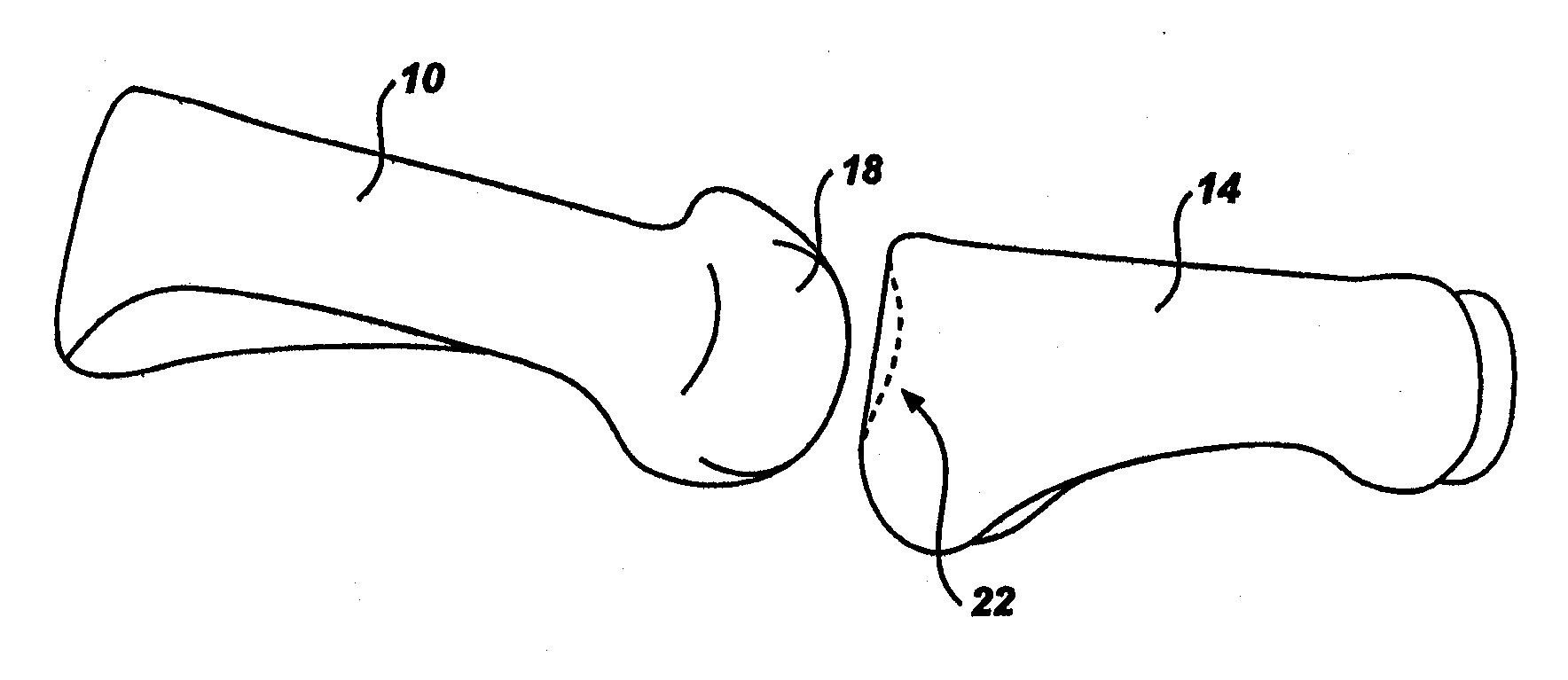
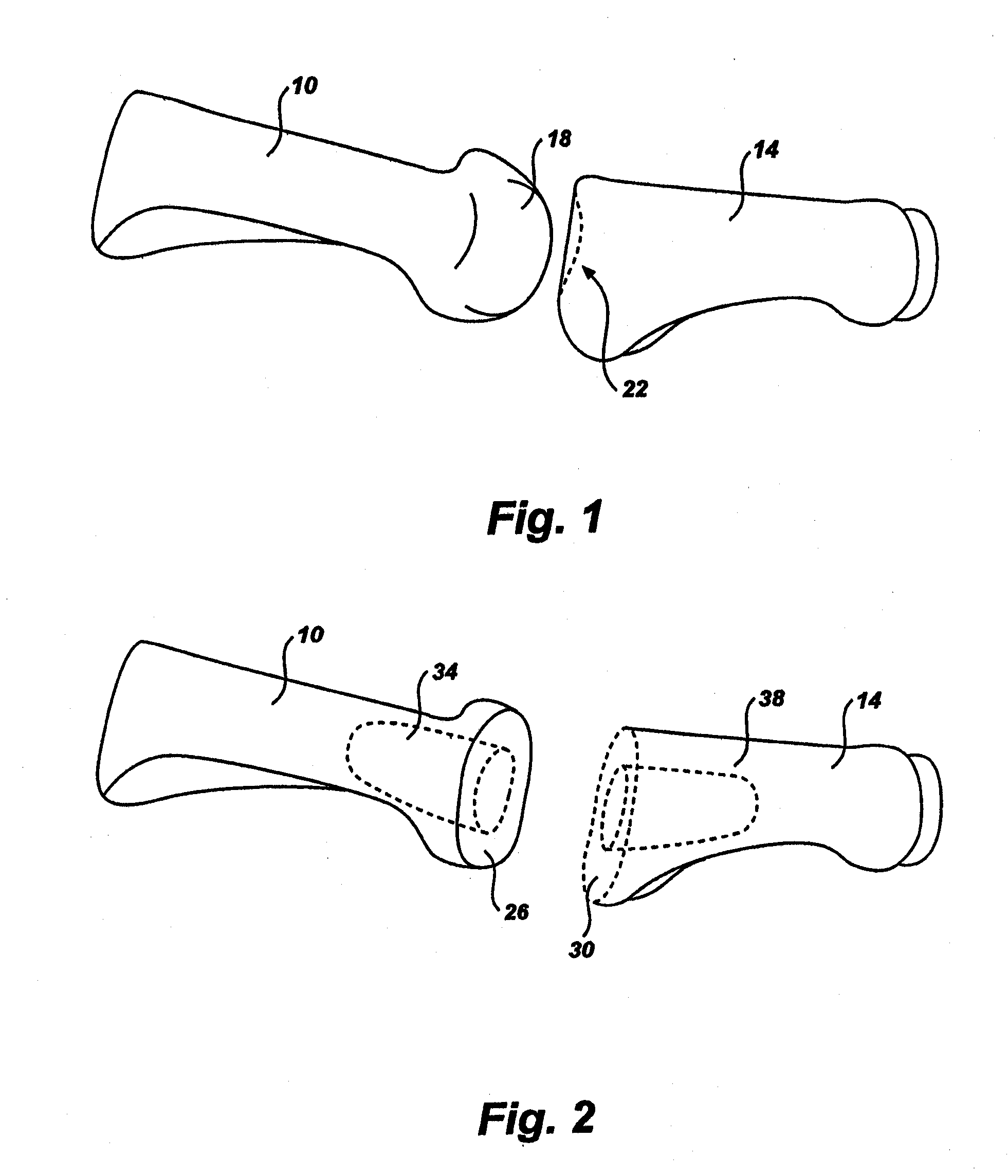
[0035]Turning now to FIG. 1, a perspective view of the bones of the proximal toe joint (the metatarsal phalangeal joint) is shown. The innermost toe joint (closest to the foot) is shown. The joint includes a metatarsal bone 10 and a phalange bone 14. The metatarsal bone 10 includes a rounded end 18 which, together with a depression 22 in the phalange bone 14 and the associated cartilage and tissue, forms the joint. The replacement of the toe joint may be necessitated by damage to the bones 10, 14 or to the cartilage and tissues of the joint. (While described in context of the first metatarsal phalangeal joint, the same anatomical presentations exist through...


PUM

PropertyMeasurementUnit
perimeteraaaaaaaaaa
distanceaaaaaaaaaa
durabilityaaaaaaaaaa

Abstract

An artificial toe joint utilizes a ball in socket joint structure and arms or side walls which are exterior to the bone. The resulting joint provides improved strength and durability, and may be used to repair joints which are not suitable for installation of a prior art artificial joint.

Description

RELATED APPLICATIONS [0001]The application claims the benefit of U.S. Provisional Patent Application Ser. No. 60 / 889,195, filed Feb. 9, 2007, which is incorporated herein in its entirety by reference.BACKGROUND OF THE INVENTION[0002]1. The Field of the Invention[0003]The present invention relates to an improved artificial toe joint. More specifically, the present invention relates to an artificial toe joint providing increased durability and reduced damage to the surrounding bone.[0004]2. State of the Art[0005]Toe joints such as the proximal metatarsal phalangeal joint, the proximal most toe joint of the foot, may become damaged from injury, etc. and may then be replaced. As a toe joint is damaged and deteriorates, symptoms may include loss of propulsion, transfer lesions, metatarsalgia (pain and inflammation of the ball of the foot), gait alterations, pain, etc. Indicators for joint replacement include: hallux limitus, hallux rigidus, hallux abducto valgus, rheumatoid arthritis, os...

Claims


Application Information

Patent Timeline
Patent Type & Authority Applications(United States)
IPC IPC(8): A61F2/42
CPCA61B17/15A61F2310/00976A61B17/1624A61B17/1637A61B17/1682A61F2/4225A61F2002/30331A61F2002/30383A61F2002/30578A61F2002/30604A61F2002/30649A61F2002/30841A61F2002/4228A61F2002/4233A61F2220/0025A61F2220/0033A61B17/1615
Inventor MORTON, TROY N.
Owner MORTON BALLARD ARTHROTECH
Why Eureka
Try Eureka