Concrete screed apparatus

Inactive Publication Date: 2011-04-21
BIODROWSKI RICHARD
View PDF20 Cites 4 Cited by
  • Summary
  • Abstract
  • Description
  • Claims
  • Application Information

AI Technical Summary

Benefits of technology

[0008]In the preferred embodiment, the inner end of the second support is vertically adjustably secured to the first support. Also, in the preferred embodiment, a laser beam apparatus is operatively secured to the first support which directs a horizontal laser beam from the first support towards the outer end of the second support. Prefer

Problems solved by technology

Moreover, this Summary is not intended for use as an aid

Method used


Image

  • Concrete screed apparatus
  • Concrete screed apparatus
  • Concrete screed apparatus

Examples


Example

[0022]Embodiments are described more fully below with reference to the accompanying figures, which form a part hereof and show, by way of illustration, specific exemplary embodiments. These embodiments are disclosed in sufficient detail to enable those skilled in the art to practice the invention. However, embodiments may be implemented in many different forms and should not be construed as being limited to the embodiments set forth herein. The following detailed description is, therefore, not to be taken in a limiting sense in that the scope of the present invention is defined only by the appended claims.

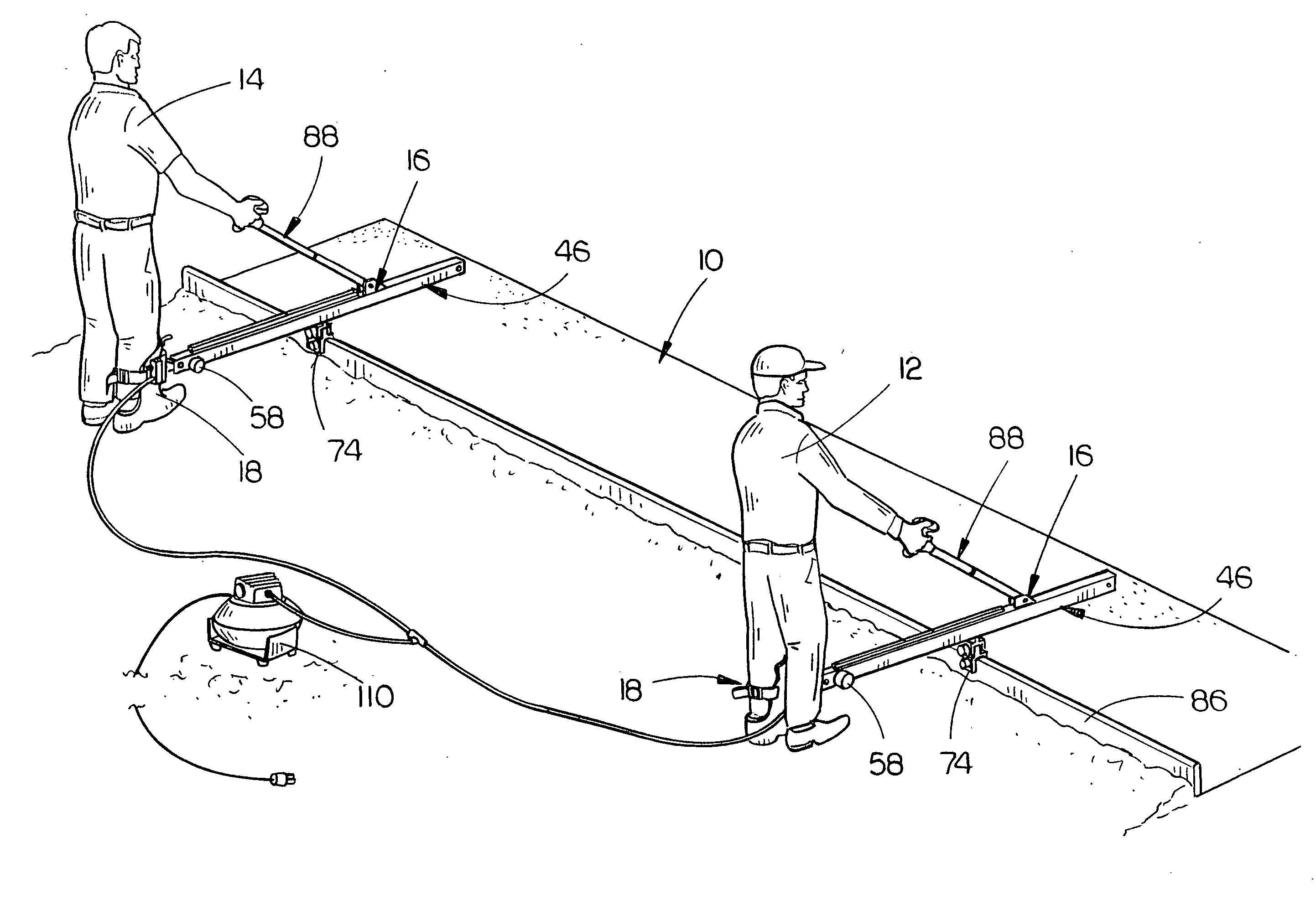
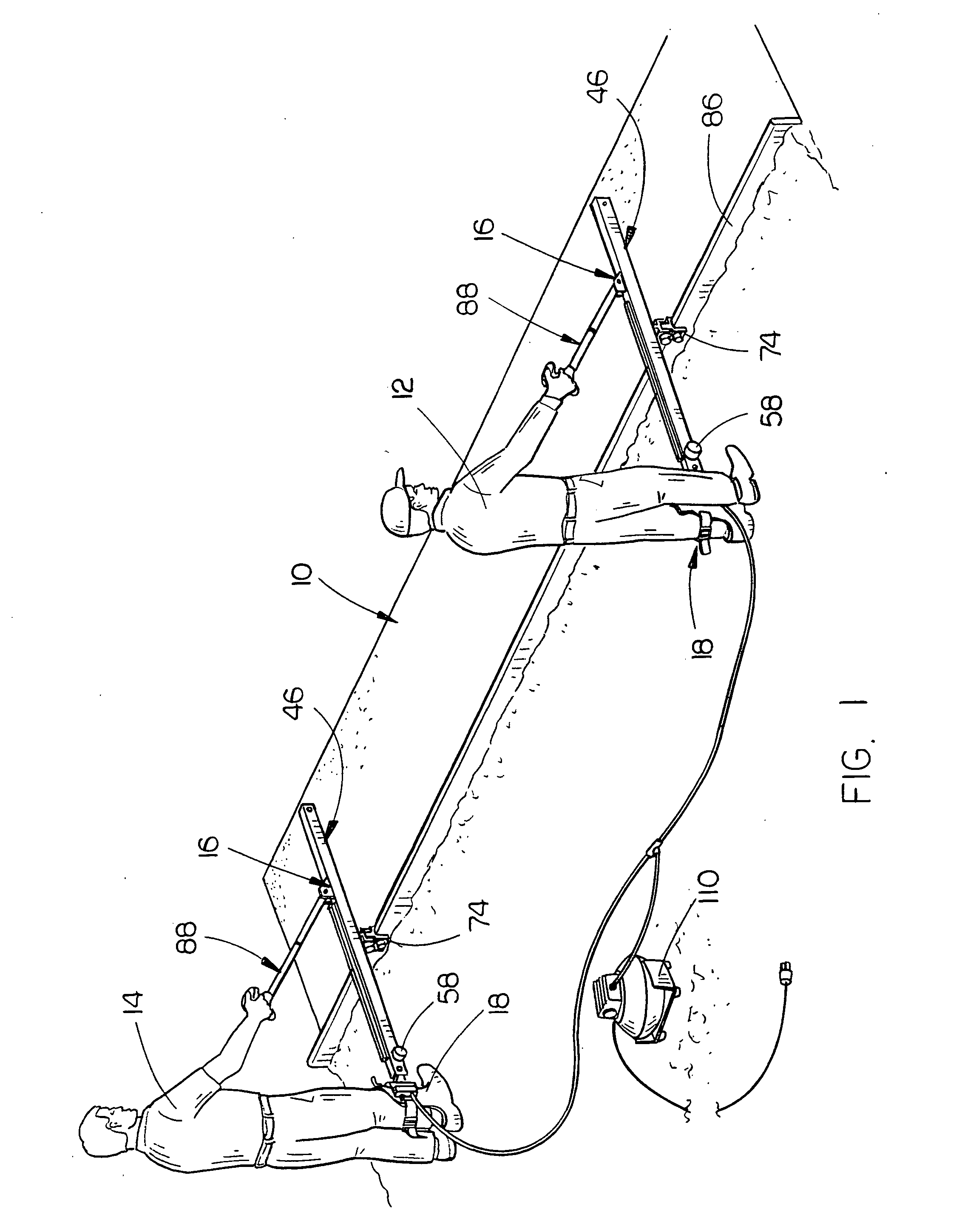
[0023]In FIG. 1, the numeral 10 refers to concrete which has been poured and which is being screeded by a pair of workers 12 and 14 which are horizontally spaced-apart. Each of the workers 12 and 14 has a concrete screed apparatus 16 associated therewith for screeding the concrete 10.

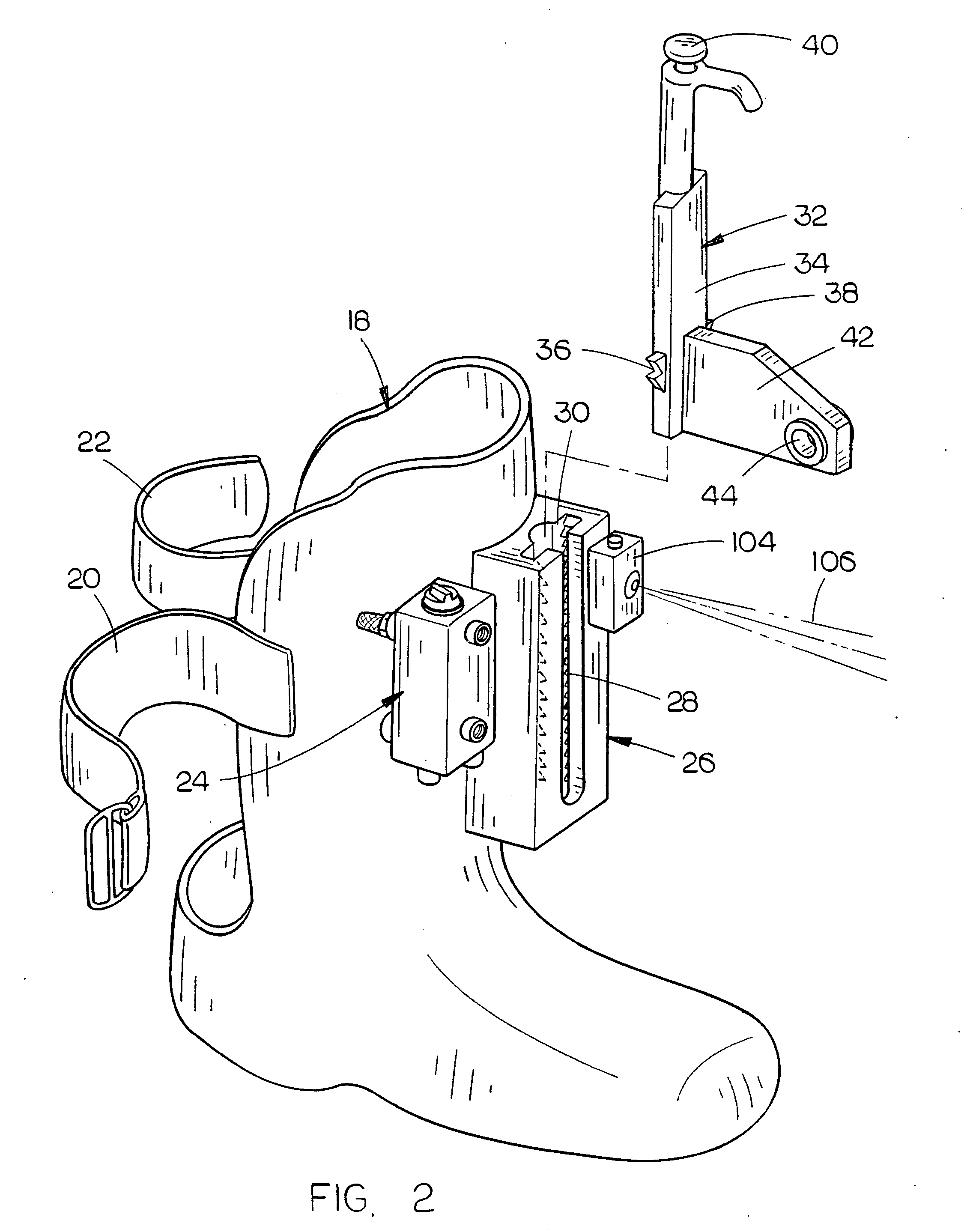
[0024]Apparatus 16 includes a first support 18 in the form of a boot or shoe into which the worker ...


PUM


Abstract

A concrete screed apparatus is provided which may be used by a pair of workers, each of whom has the screed apparatus mounted to one of their legs or feet. The screed apparatus enables concrete to be easily screeded and properly finished without the workers doing the same on their knees or bending from the waist. The screed apparatus is adapted to move a screed board back and forth across the concrete to be finished which is also vibrated as it is being screeded.

Description

BACKGROUND OF THE INVENTION[0001]1. Field of the Invention[0002]This invention relates to a concrete screed apparatus and more particularly to a concrete screed apparatus which is preferably used by a pair of spaced-apart workers, wherein each of the workers have a concrete screed apparatus operatively secured to a leg of the worker so that the two workers may screed concrete.[0003]2. Description of the Related Art[0004]When concrete is being poured and finished, a pair of workers are normally positioned at the opposite ends of a screed board with the screed board being moved back and forth to level the concrete. Usually, the workers must perform the screeding operation while on their knees or in a kneeling position which is extremely tiresome and difficult.SUMMARY OF THE INVENTION[0005]This Summary is provided to introduce a selection of concepts in a simplified form that are further described below in the Detailed Description. This Summary is not intended to identify key aspects o...

Claims


Application Information

Patent Timeline
IPC IPC(8): E01C19/38E01C19/22
CPCE04F21/24E01C19/402E04F21/242
Inventor BIODROWSKI, RICHARD
Owner BIODROWSKI RICHARD
Why Eureka
Try Eureka