Imaging device and imaging apparatus

Inactive Publication Date: 2011-05-12
FUJIFILM CORP
View PDF10 Cites 180 Cited by
  • Summary
  • Abstract
  • Description
  • Claims
  • Application Information

AI Technical Summary

Benefits of technology

[0019]The invention can provide an imaging device and an image apparatus, which can simultaneously perform the imaging of a recording image and

Problems solved by technology

Accordingly, the contrast detection method has a disadvantage in low AF speed.
However, the pupil division type phase difference detection method is disadvantage

Method used


Image

  • Imaging device and imaging apparatus
  • Imaging device and imaging apparatus
  • Imaging device and imaging apparatus

Examples


Example

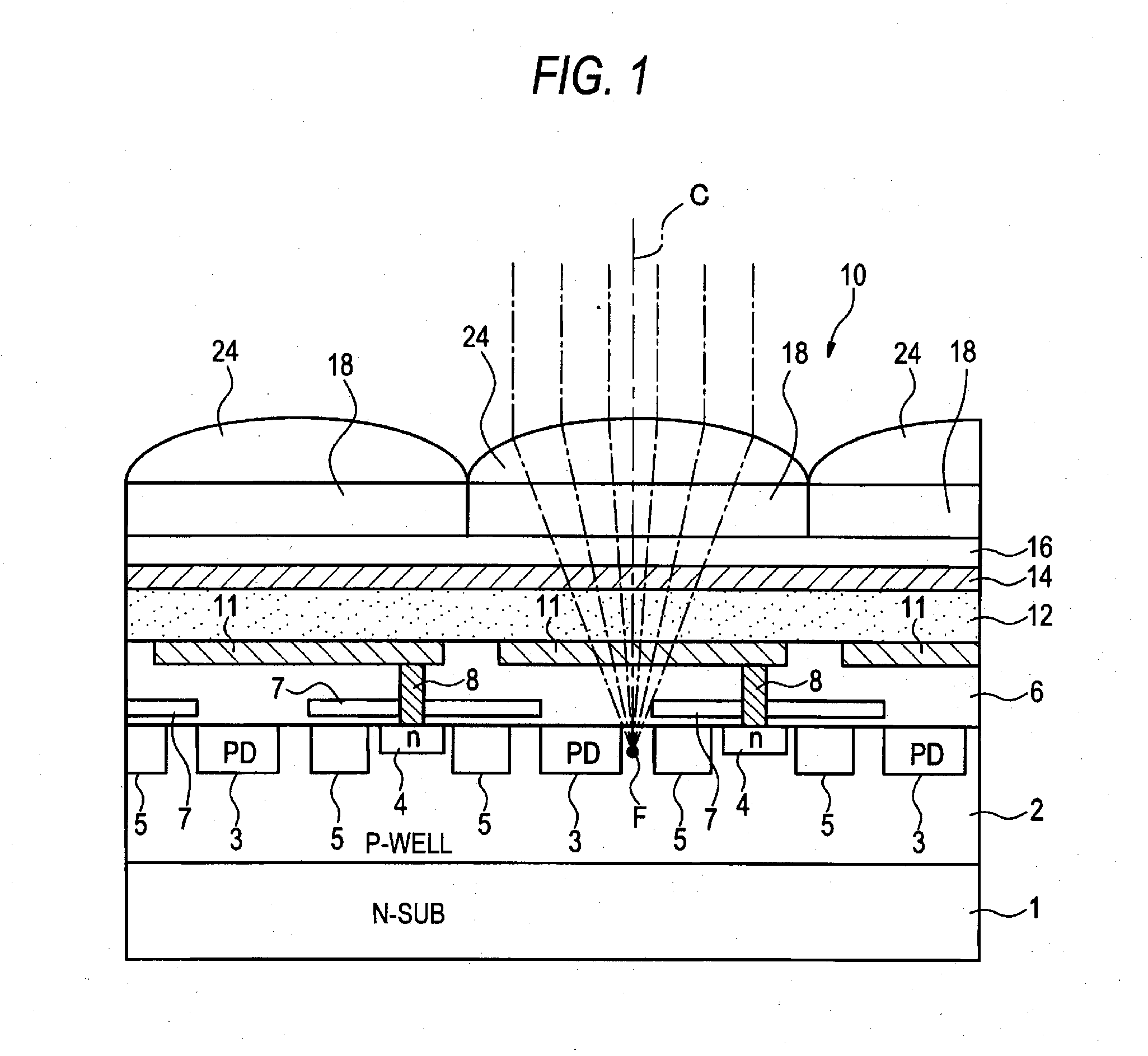
[0030]FIG. 1 is a cross-sectional view illustrating an imaging device. An imaging device 10 has a semiconductor substrate that is an n-type silicon substrate 1 on which a p-well layer 2 is formed. FIG. 1 illustrates a state in which a light-incidence-side of the imaging device 10 is set to be an upper side. Thus, in the following description made with reference to FIG. 1, the direction of the light-incidence-side of the imaging device 10 is assumed to be an “upper” direction or a “top direction”. The opposite direction of the light-incidence-side is assumed to be a “lower” direction or a “bottom direction”.

[0031]Embedded type photodiodes 3, n-type impurity diffused regions 4, and signal reading portions 5 are provided in the p-well layer 2. The signal reading portions 5 are provided respectively corresponding to each photodiode 3 and each impurity diffused region 4 one-by-one.

[0032]A transparent insulating film 6 is provided on the p-well layer 2. A plurality of pixel electrodes 11 ...


PUM


Abstract

An imaging device includes a plurality of pixels each of which includes a microlens, first and second photoelectric conversion portions. The first photoelectric conversion portion is between the microlens and a focal point of the microlens. The second photoelectric conversion portion is at a position being different from that of the focal point on a plane which is parallel to an imaging plane and which contains the focal point, and has a photoelectric conversion region deviated from an optical axis of the microlens in a direction of the imaging plane. The plurality of pixels includes a first pixel group and a second pixel group. The photoelectric conversion region is deviated from the optical axis in the direction in the first pixel group. The photoelectric conversion region is deviated from the optical axis in the direction to be opposite to the first pixel group in the second pixel group.

Description

CROSS-REFERENCE TO RELATED APPLICATIONS[0001]This application claims the benefit of Japanese Patent Application No. 2009-257122, filed on Nov. 10, 2009, the entire contents of which are hereby incorporated by reference, the same as if set forth at length; the entire of which are incorporated herein by reference.BACKGROUND OF THE INVENTION[0002]1. Technical Field[0003]The present invention relates to an imaging device and an imaging apparatus.[0004]2. Description of Related Art[0005]A contrast detection method and a pupil division type phase difference detection method have been known as methods for performing autofocus (AF) in an imaging apparatus such as a digital camera.[0006]The contrast detection method can utilize an imaging device for a recording image. However, it is necessary to capture a plurality of images by shifting a focal point. Accordingly, the contrast detection method has a disadvantage in low AF speed.[0007]On the other hand, the pupil division type phase differenc...

Claims


Application Information

Patent Timeline
IPC IPC(8): H04N5/335H01L27/146
CPCH01L27/14625H01L27/14627H04N5/374H01L27/14643H01L27/1463H04N25/76
Inventor KAWAI, TOMOYUKI
Owner FUJIFILM CORP
Why Eureka
Try Eureka