System and Method for Stabilizing Corneal Tissue After Treatment

Inactive Publication Date: 2011-05-19
AVEDRO
View PDF100 Cites 0 Cited by
  • Summary
  • Abstract
  • Description
  • Claims
  • Application Information

AI Technical Summary

Benefits of technology

According to one embodiment of the invention, a method for applying therapy to an eye is described. The method comprises the steps of positioning an electrical energy conducting element in contact with a surface of an eye; applying electrical energy to an area of the eye with the electrical energy conductin

Problems solved by technology

Wound healing may occur in response to the application of the treatment and may produce

Method used


Image

  • System and Method for Stabilizing Corneal Tissue After Treatment
  • System and Method for Stabilizing Corneal Tissue After Treatment
  • System and Method for Stabilizing Corneal Tissue After Treatment

Examples


Embodiment Construction

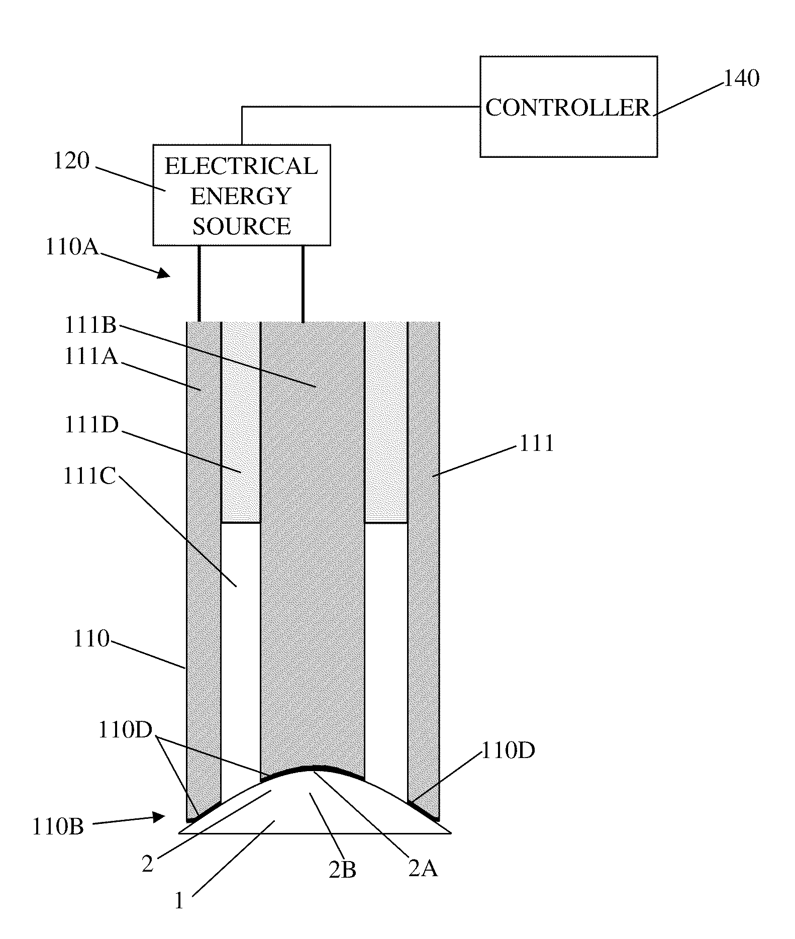
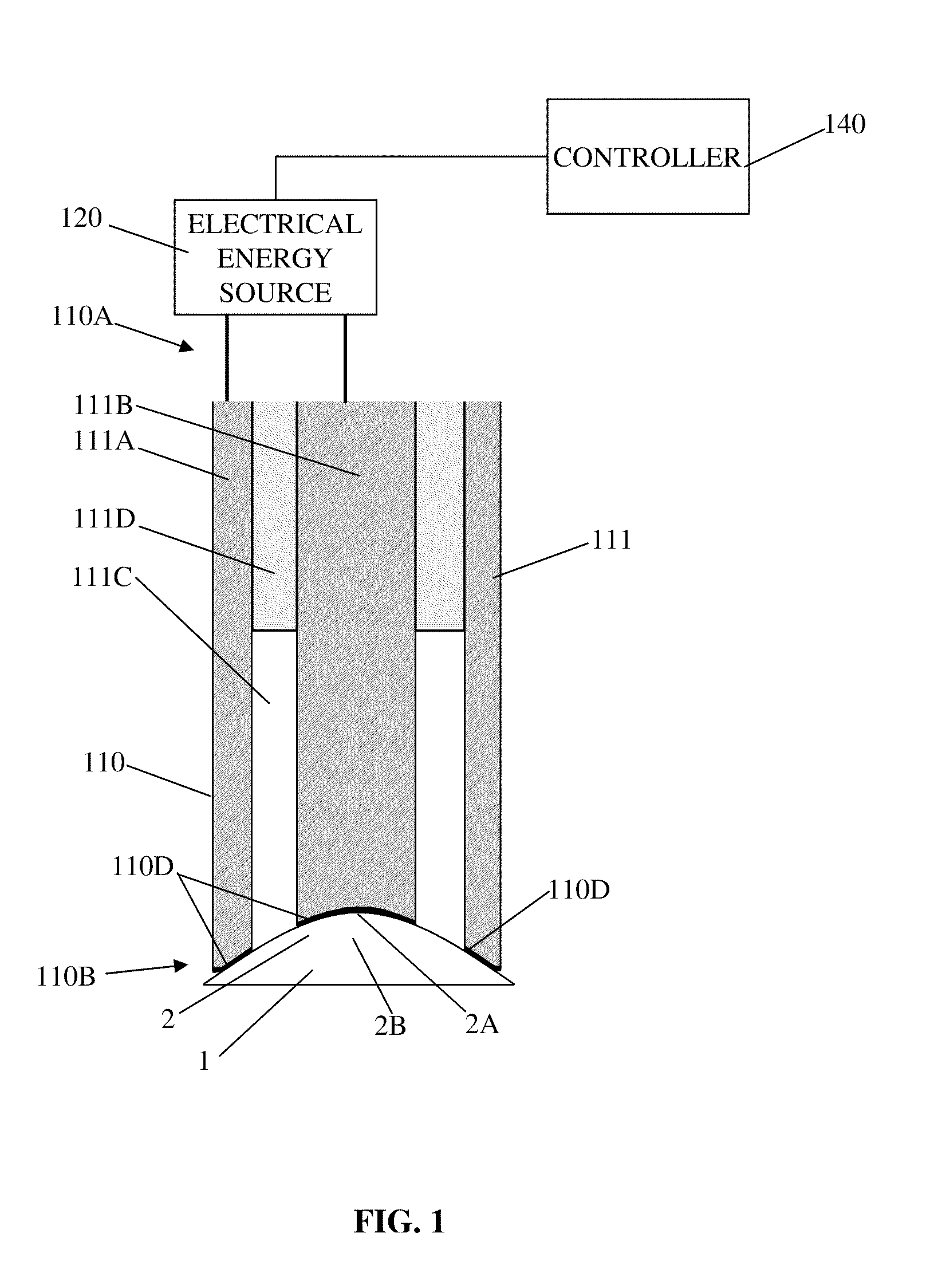
FIG. 1 illustrates an example system for applying energy to a cornea 2 of an eye 1 to generate heat and cause reshaping of the cornea. In particular, FIG. 1 shows an applicator 110 with an electrical energy conducting element 111 that is operably connected to an electrical energy source 120, for example, via conventional conducting cables. The electrical energy conducting element 111 extends from a proximal end 110A to a distal end 110B of the applicator 110. The electrical energy conducting element 111 conducts electrical energy from the source 120 to the distal end 110B to apply energy to the cornea 2, which is positioned at the distal end 110B. In particular, the electrical energy source 120 may include a microwave oscillator for generating microwave energy. For example, the oscillator may operate at a microwave frequency range of 400 MHz to 3000 MHz, and more specifically at a frequency of around 915 MHz or 2450 MHz. As used herein, the term “microwave” may correspond to a frequ...


PUM

PropertyMeasurementUnit
Energyaaaaaaaaaa

Abstract

Systems and methods stabilize corneal tissue after treatment of the corneal tissue. For example, thermokeratoplasty may be applied to the corneal tissue to address disorders associated with abnormal shaping of the cornea. To stabilize the desired structural changes caused by the treatment, embodiments apply ophthalmic formulations that help to inhibit wound healing. Wound healing may occur in response to the application of the treatment and may produce further structural changes that mitigate or alter the desired effects of the treatment.

Description

BACKGROUND OF THE INVENTION1. Field of the InventionThe invention pertains to the field of keratoplasty and, more particularly, to systems and methods for stabilizing corneal tissue after treatment of the corneal tissue.2. Description of Related ArtA variety of eye disorders, such as myopia, hyperopia, astigmatism, and keratoconus involve abnormal shaping of the cornea. Keratoplasty reshapes the cornea to correct such disorders. For example, with myopia, the shape of the cornea causes the refractive power of an eye to be excessive. Parallel rays of light are focused in front of the retina, producing a blurred image of objects at a distance. Flattening aspects of the cornea's shape about the visual axis through keratoplasty decreases the refractive power of an eye with myopia and causes the image to be properly focused at the retina.In another example, with hyperopia, the shape of the cornea causes the refractive power of an eye to be insufficient. Parallel rays of light are focused ...

Claims


Application Information

Patent Timeline
IPC IPC(8): A61B18/02A61B18/18
CPCA61B18/1815A61B2018/00029A61F9/007A61F9/0079A61M2210/0612A61F2009/00872A61K38/1841A61M35/00A61F9/013A61P27/02
Inventor MULLER, DAVIDMARSHALL, JOHN
Owner AVEDRO
Why Eureka
Try Eureka