
Fitting for hanging a chair, and chair having such a fitting

a technology for hanging chairs and fittings, which is applied in the field of fittings for hanging chairs, can solve the problems of creating a lot of space for cleaning the floor surface, and achieve the effect of reducing the amount of space for cleaning

Inactive Publication Date: 2011-05-26
MOD ART DESIGNE
View PDF5 Cites 2 Cited by
  • Summary
  • Abstract
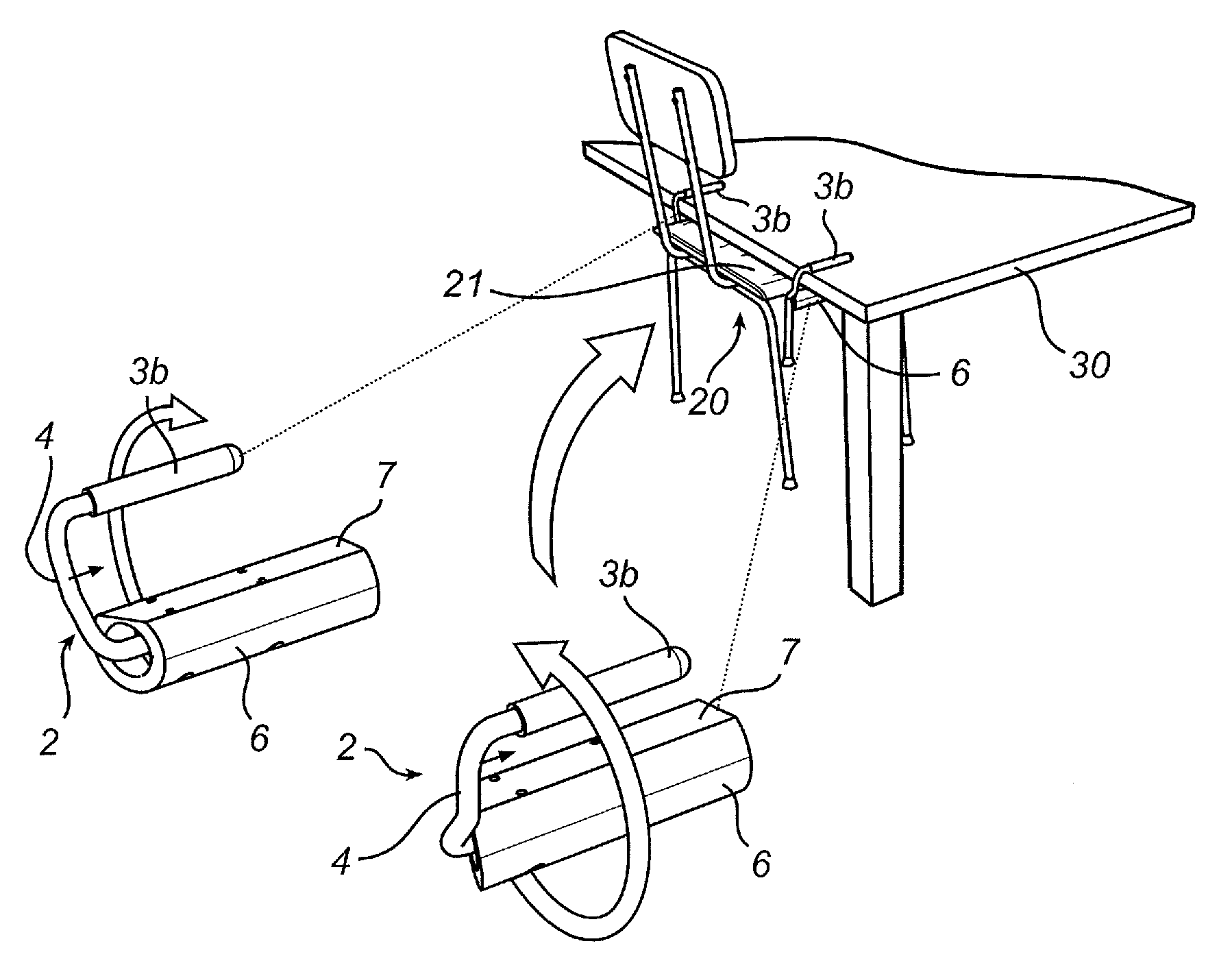
  • Description
  • Claims
  • Application Information

AI Technical Summary

Benefits of technology

[0008]By designing a fitting in this way, such a fitting can be used by being secured to a chair such that the chair is moved aside during cleaning, etc. Two fittings are preferably secured to the chair, preferably at opposite side edges of the chair. In this way, the chair can be hung on a table top. The fitting can be secured such that the holder is secured to the seat of the chair and the yoke extends directly across the seat of the chair. This can have the effect that the chair, when hung on the table, comes to a height such that the seat is located directly under the table top. When the chair comes up so high, this creates a lot of space for cleaning the floor surface under the table. The yoke can extend above the seat in the vertical direction such that the vertical distance between the yoke and the seat is at least the same length as the thickness of a table top. In this way, the yoke can bear on the upper face of the table top, and the seat can be located under the table top. An advantage of the invention is also that the fitting can be secured to a chair without armrests. Such a chair can then be hung on a table without the need for strenuous lifting and turning of the chair. Moreover, the two positions of the yoke mean that, in the first position, it can be retracted below the seat of the chair so as not to be in the way.
[0009]When the yoke is described as extending in a vertical direction, this means a direction at right angles to the substantially horizontal plane in which the seat of the chair lies when the chair is in the upright position. The yoke extends further along the vertical direction toward one or other end in the two positions than the position along the vertical direction where the horizontal plane of the seat is substantially located.
[0010]In one embodiment, the holder can be designed to be secured to the underside of a seat. This means that the fitting can be mounted on a chair without interfering with the appearance of the chair and without affecting the seating comfort. When the yoke is located in the second position, it extends out from the holder on the underside of the seat, outside and above the seat.
[0011]In a further embodiment, the yoke, in the first position, can extend toward the underside of the seat. In this way, the yoke, in the first position, is not only able to be lowered so as not to get in the way of someone sitting on the chair, it can also be turned in under the seat so as not to be visible. The fact that the yoke can extend toward the underside of the seat means that the yoke can extend from the point of attachment of the holder on the chair toward an area of the underside of the seat alongside the point of attachment. The yoke can extend in a direction that is substantially parallel to the plane in which the seat lies, but it can also be at a slight angle to the seat, for example such that the yoke bears against the underside of the seat.
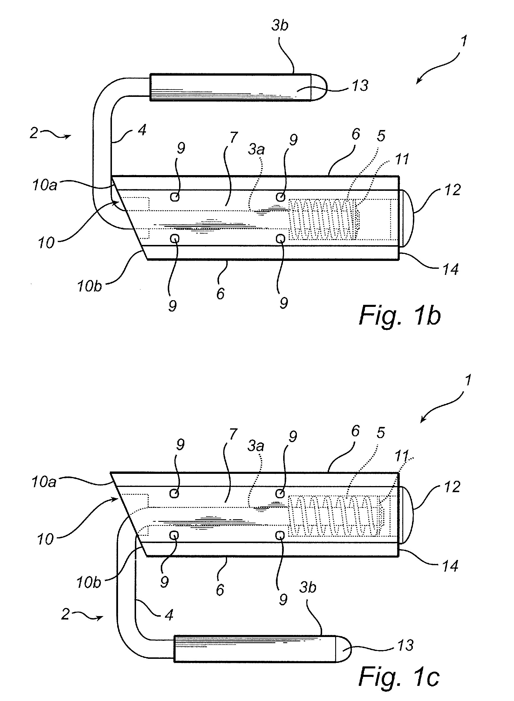
[0012]In one embodiment, the fitting can further comprise a spring, wherein the spring can be arranged to hold the yoke in the first and / or second position by means of a spring force. The effect achieved by this is that the yoke can be sprung toward the first or second position when the yoke is driven from one position to the other. This also means that the yoke is held steadily in a given position.
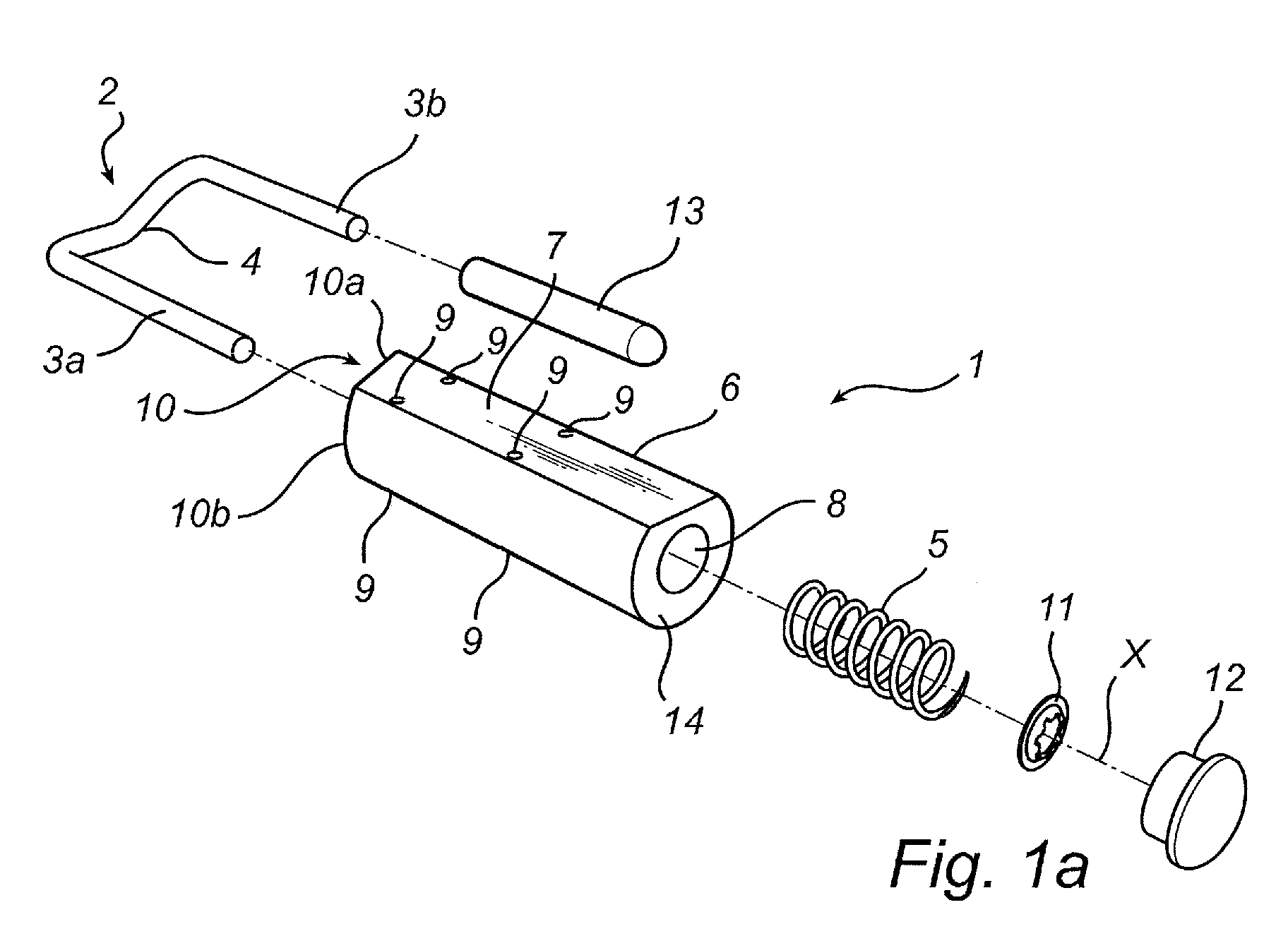
[0013]In one embodiment, the holder can be coupled to the spring and to a first part of the yoke. In a further embodiment, the holder can extend along a longitudinal axis, and the yoke can be rotatable relative to the holder around the longitudinal axis. In this way, the yoke is made movable relative to the chair, since the holder is secured to the chair. The holder can extend along a longitudinal axis, and the first part of the yoke can be coupled to the holder such that when the yoke moves relative to the holder, the first part of the yoke turns around the longitudinal axis. A second part of the yoke can extend away from the longitudinal axis. In this way, the second part of the yoke moves between the two positions when the first part of the yoke is turned around the longitudinal axis. The second part of the yoke can then extend away from the longitudinal axis, inward under the seat surface, when the first part of the yoke has been turned such that the yoke is located in the first position, and, moreover, the second part of the yoke can extend away from the longitudinal axis, outward and upward from the seat, when the first part of the yoke has been turned such that the yoke is located in the second position.

Problems solved by technology

When the chair comes up so high, this creates a lot of space for cleaning the floor surface under the table.

Method used


Image

  • Fitting for hanging a chair, and chair having such a fitting
  • Fitting for hanging a chair, and chair having such a fitting
  • Fitting for hanging a chair, and chair having such a fitting

Examples


Embodiment Construction

[0027]The present invention is described in more detail below with reference to the accompanying drawings in which preferred embodiments of the invention are shown. However, the invention can be implemented in many different forms and must not be interpreted as being limited to the embodiments presented here. Rather, these embodiments are intended to ensure that the present description is clear and comprehensive and fully conveys the scope of the invention to a person skilled in the art. In the drawings, the same numbers refer to the same elements.

[0028]FIGS. 1a, 1b and 1c show a fitting 1 according to the invention with a yoke 2 which has a U-shape with a first part 3a, a second part 3b and a middle part 4. The first part 3a and second part 3b of the yoke are substantially parallel and are separated by the middle part 4. Substantially right angles form between the middle part 4 and the first 3a and second 3b parts, respectively. The middle part 4 is slightly bent along the extent b...


PUM


Abstract

The present invention relates to a fitting (1) for mounting on a chair (20) for the purpose of hanging the chair on a table top (30), characterized in that the fitting (1) comprises a holder (6), designed to be secured to a seat (21), and a yoke (2) coupled to the holder (6), said yoke (2) being movable relative to the holder (6), said yoke (2) being able to be shifted between a first position and a second position when it is mounted on the chair (20), and said yoke (2), in the first position, extending below the seat (21) of the chair in a vertical direction, and, in the second position, extending above the seat (21) of the chair in the vertical direction, when the chair (20) is upright.The invention further relates to a chair (20) with two such fittings (1) mounted on the chair (20).

Description

TECHNICAL FIELD[0001]The present invention relates to a fitting for hanging a chair on the edge of a table or another piece of furniture.BACKGROUND OF THE INVENTION[0002]When cleaning floors in premises in which there are chairs and tables, it is usually necessary to lift or move the chairs in order to gain access to the surface under the table. If the chairs are provided with armrests, the latter can be used to hang the chair on the table edge. However, the height difference between the armrests and the table top when the chair is standing on the floor is often not particularly great, which means that the chair, when it is hung by the armrests on the table edge, is hanging less than ten centimeters above the floor surface. This means that cleaning the floor surface under the table, for example with a mop, is still extremely difficult, because the chair is hanging in the way.[0003]For chairs without armrests, an alternative way of solving the problem of the chair not being far enoug...

Claims


Application Information

Patent Timeline
Patent Type & Authority Applications(United States)
IPC IPC(8): A47C31/00F16M13/02
CPCA47C9/022A47C7/62
Inventor LINDBOM, ANDERS
Owner MOD ART DESIGNE
Learn More