Framing Corner Joint and Method of Manufacture

a corner joint and manufacturing method technology, applied in the field of framing corner joints and manufacturing methods, can solve the problems of not being able to be easily and/or deleteriously affecting the sealing properties of corner joints, etc., to achieve the effect of increasing the cost of framing corners and being able to be welded to each other

Active Publication Date: 2011-05-26
MILGARD MFG LLC
View PDF28 Cites 6 Cited by
  • Summary
  • Abstract
  • Description
  • Claims
  • Application Information

AI Technical Summary

Benefits of technology

[0003]When joining the ends of lineal rails at the corners of structural sash and framing members of building windows, for example, the mitered corners of the lineal rails can be thermally welded to each other when the rails are of vinyl construction. Fiberglass-reinforced composite rails have many advantages over vinyl, but cannot readily be welded to each other. Mechanical joining has been used, increasing the cost of the framing corner and / or deleteriously affecting the sealing properties of the corner joint. One objective of the present disclosure is to provide the ability to weld the corners of a fiberglass-reinforced composite window or door framing to obtain the sealing benefits of a welded joint while retaining other benefits of using fiberglass-reinforced composites.

Problems solved by technology

Fiberglass-reinforced composite rails have many advantages over vinyl, but cannot readily be welded to each other.
Mechanical joining has been used, increasing the cost of the framing corner and / or deleteriously affecting the sealing properties of the corner joint.

Method used


Image

  • Framing Corner Joint and Method of Manufacture
  • Framing Corner Joint and Method of Manufacture
  • Framing Corner Joint and Method of Manufacture

Examples


Embodiment Construction

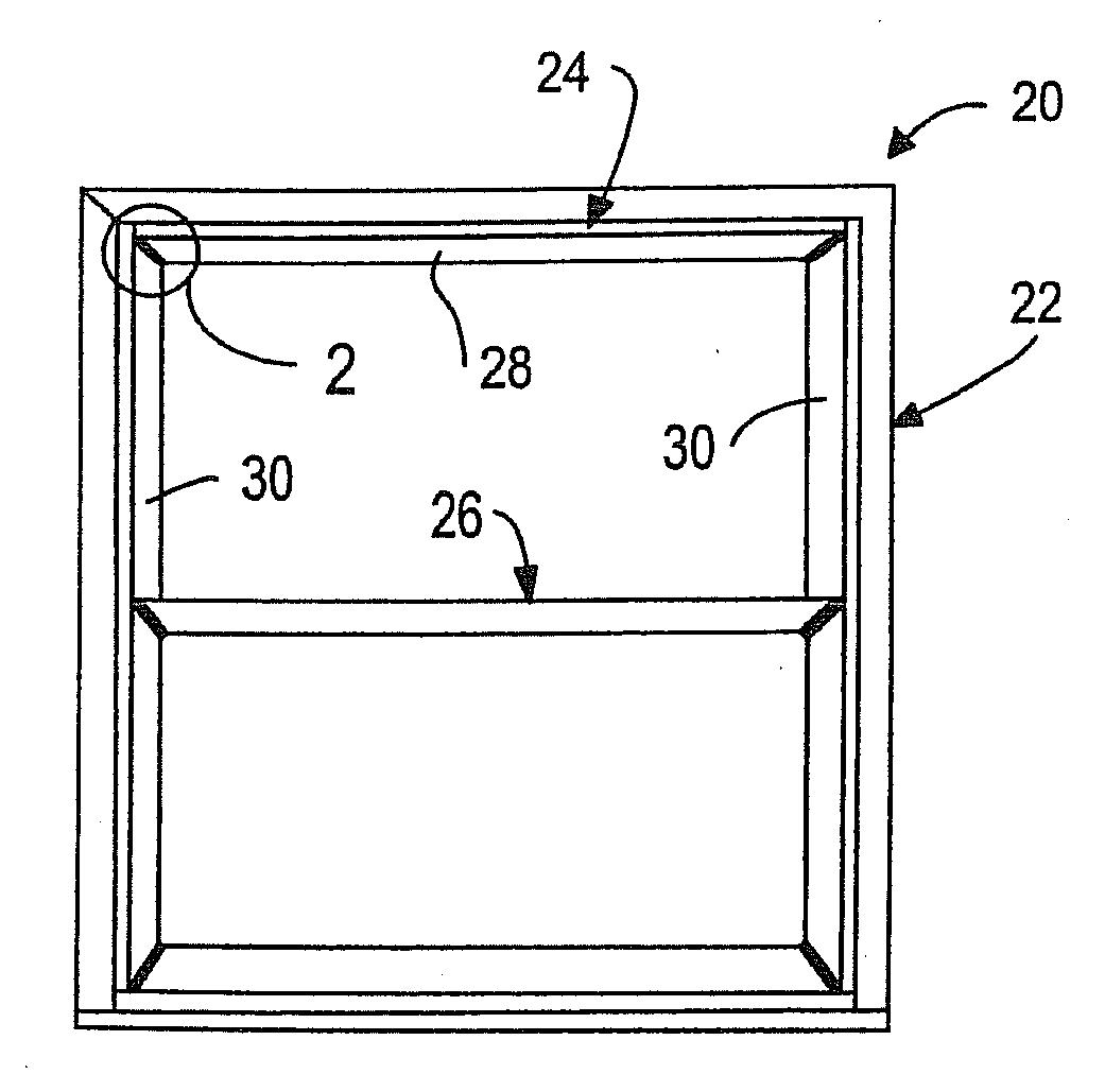
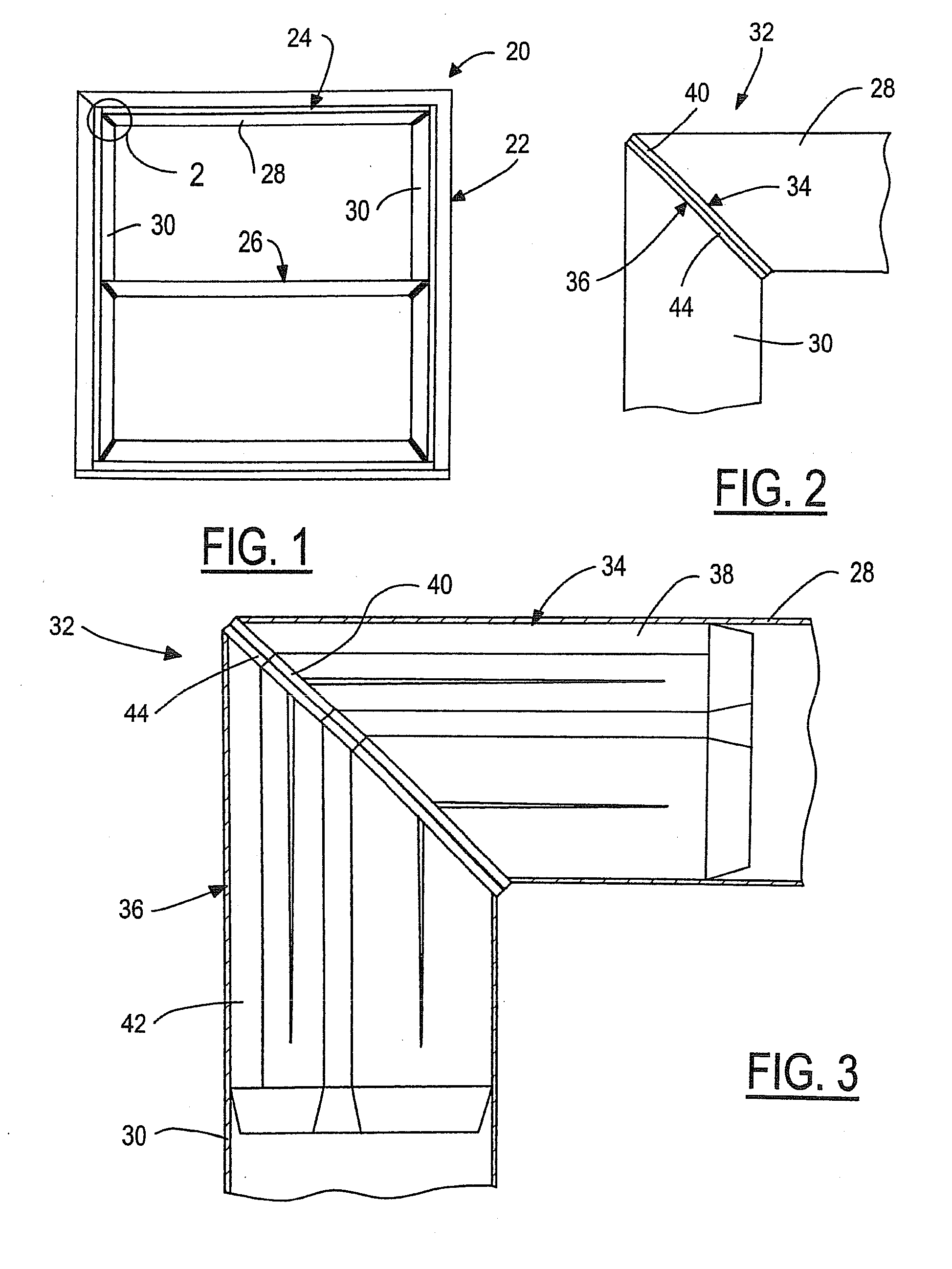
[0012]FIG. 1 illustrates a building window assembly 20 in accordance with one exemplary embodiment of the present disclosure. Window assembly 20 includes an outer framing 22 that presents one type of framing structure, an upper sash 24 that presents another type of framing structure, and a lower sash 26 that presents a framing structure similar to upper sash 24. Upper sash 24 includes upper and lower framing rails 28 and framing sides rails 30. Lower sash 26 may be of similar construction. Framing rails 28,30 are of elongated fiberglass-reinforced resin construction having interiors of predetermined geometry and mitered ends at angles of 45° where the rails are joined to each other. At least the ends of the rails are open and hollow. The central portions of the rails may be hollow, or may be filled with insulating material such as polyurethane foam. The interiors of the rails are mirror images of each other at each corner.

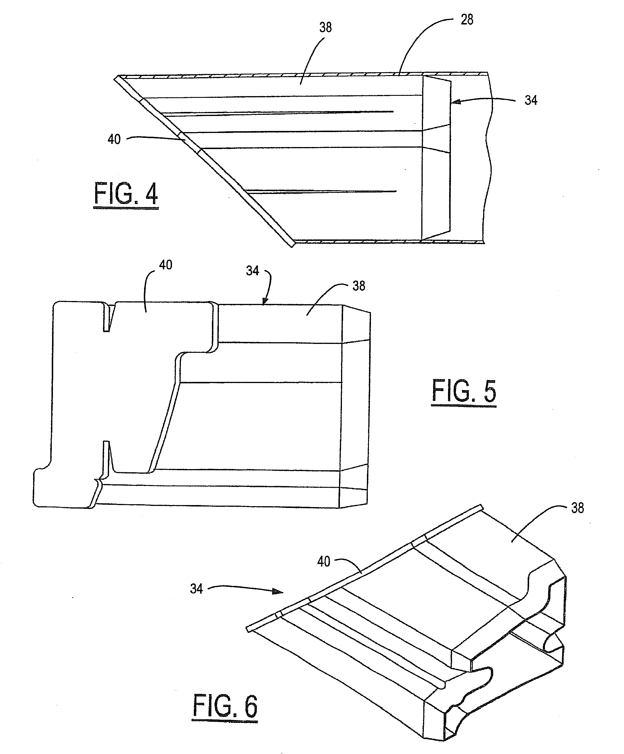
[0013]FIGS. 2 and 3 illustrate a framing corner joint 32 in a...


PUM

PropertyMeasurementUnit
anglesaaaaaaaaaa
angleaaaaaaaaaa
anglesaaaaaaaaaa

Abstract

A framing corner joint includes first and second framing rails of fiberglass-reinforced resin construction. The first and second framing rails have hollow mitered ends. A pair of thermoplastic plugs are received in the mitered ends of the respective framing rails. Each of the plugs includes a body inserted into the hollow interior of an associated framing rail and a flat plug flange at an angle of 45° to the body. The plug flanges extend outwardly from the peripheries of the bodies between the rail ends and have flat end faces that are bonded to each other. The bodies of the plugs preferably are hollow, and preferably are received by interference press-fit within the ends of the rails. The plug flanges of the plugs preferably are welded to each other.

Description

CROSS-REFERENCE TO RELATED APPLICATION[0001]This application is a divisional of U.S. patent application Ser. No. 11 / 397,290 filed on Apr. 4, 2006. The disclosures of the above application is incorporated herein by reference in its entirety.[0002]The present disclosure relates to corner joints in framing structures for windows and / or doors for example, and to a method of making such a corner joint.BACKGROUND AND SUMMARY OF THE DISCLOSURE[0003]When joining the ends of lineal rails at the corners of structural sash and framing members of building windows, for example, the mitered corners of the lineal rails can be thermally welded to each other when the rails are of vinyl construction. Fiberglass-reinforced composite rails have many advantages over vinyl, but cannot readily be welded to each other. Mechanical joining has been used, increasing the cost of the framing corner and / or deleteriously affecting the sealing properties of the corner joint. One objective of the present disclosure...

Claims


Application Information

Patent Timeline
Patent Type & Authority Applications(United States)
IPC IPC(8): B32B3/02B29C65/02B29C65/48
CPCE06B3/9608Y10T428/192Y10T29/49904B29C66/73921B29C66/636B29C65/4895B29C66/3282B29C66/1162B29C66/7212B29L2031/005B29C66/71B29C66/52431B29C65/02B29K2309/08B29K2027/06B29K2075/00
Inventor BROWN, RANDY J.
Owner MILGARD MFG LLC
Why Eureka
Try Eureka