Mini-Cell, On-Orbit, Temperature Re-Calibration Apparatus and Method

a temperature recalibration and mini-cell technology, applied in the field of infrared (ir) instruments, can solve the problems of temperature sensor drift, measurement system using on-board blackbodies as reference points, and inability to accurately determine the temperature of the plateau, etc., to achieve the effect of precise plateau temperatur

Active Publication Date: 2011-05-26
UTAH STATE UNIVERSITY
View PDF6 Cites 17 Cited by
  • Summary
  • Abstract
  • Description
  • Claims
  • Application Information

AI Technical Summary

Benefits of technology

[0011]In selected embodiments, a heat transfer device (e.g., heater, thermoelectric cooler (TEC)) located between the cell and the radiant portion of the blackbody may be used to heat or cool the phase-change material to effect the phase change. One or more temperature sensors (e.g., thermistors, platinum resistance thermometers (PRTs)) to be calibrated may record the temperature change with time and identify the temperature plateau corresponding to the phase change. Additionally, the state of the material may be measured by displacement of the container, thus a more precise plateau temperature may be measured at a threshold state of the material, corresponding to that phase change.

Problems solved by technology

However, the accuracy and stability of temperature sensors used in such calibration procedures can be affected by numerous factors.
For example, measurement systems using on-board blackbodies as reference points are subject to temperature sensor drift.
Any of these factors may cause drift and necessitate re-calibration.
This Simultaneous Nadir Overpass (SNO) method allows offsets between instruments to be corrected, but does not allow absolute calibration.

Method used


Image

  • Mini-Cell, On-Orbit, Temperature Re-Calibration Apparatus and Method
  • Mini-Cell, On-Orbit, Temperature Re-Calibration Apparatus and Method
  • Mini-Cell, On-Orbit, Temperature Re-Calibration Apparatus and Method

Examples


Embodiment Construction

[0028]It will be readily understood that the components of the present invention, as generally described and illustrated in the drawings herein, could be arranged and designed in a wide variety of different configurations. Thus, the following more detailed description of the embodiments of the system and method of the present invention, as represented in the drawings, is not intended to limit the scope of the invention, but is merely representative of various embodiments of the invention. The illustrated embodiments of the invention will be best understood by reference to the drawings.

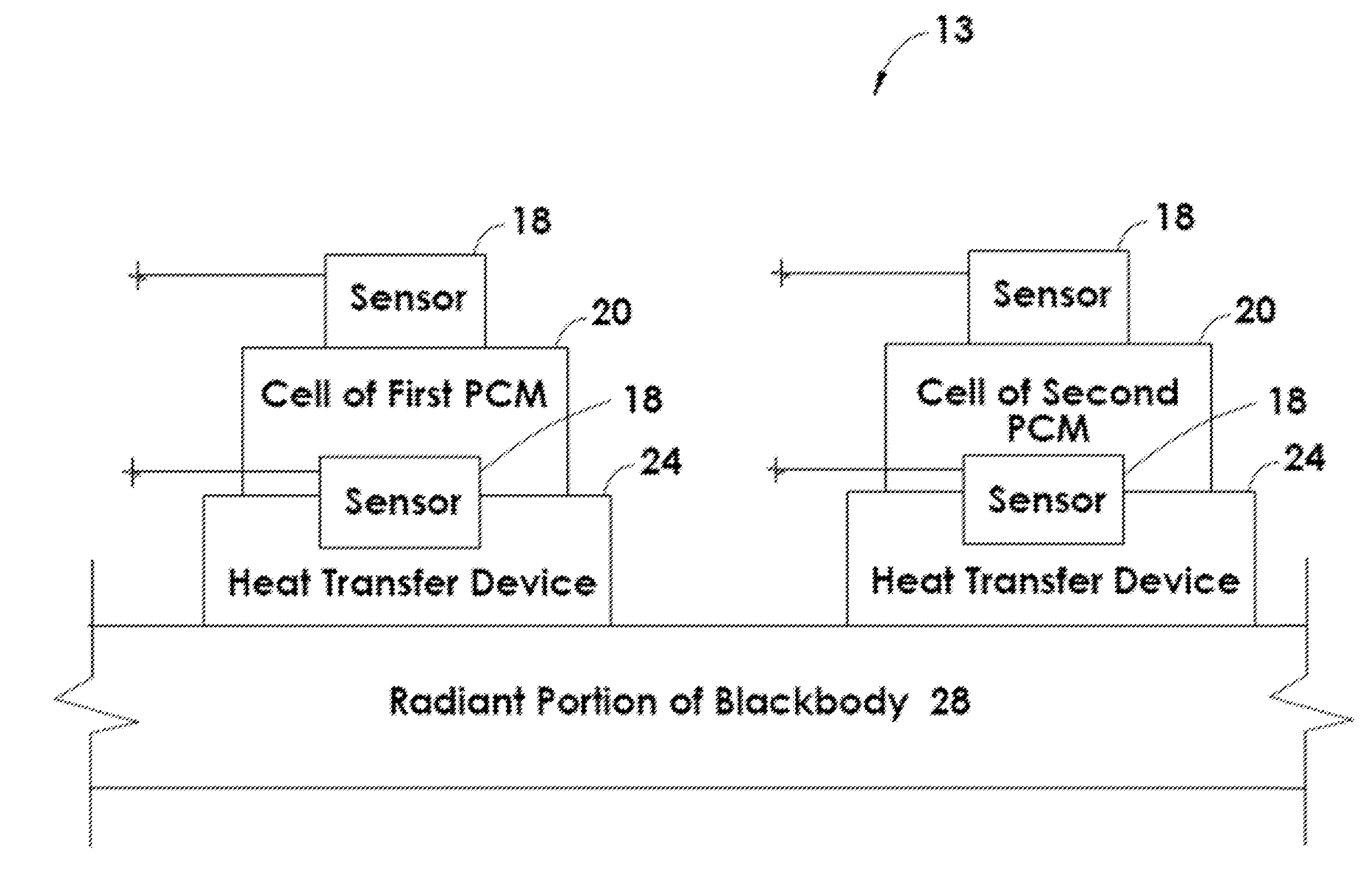
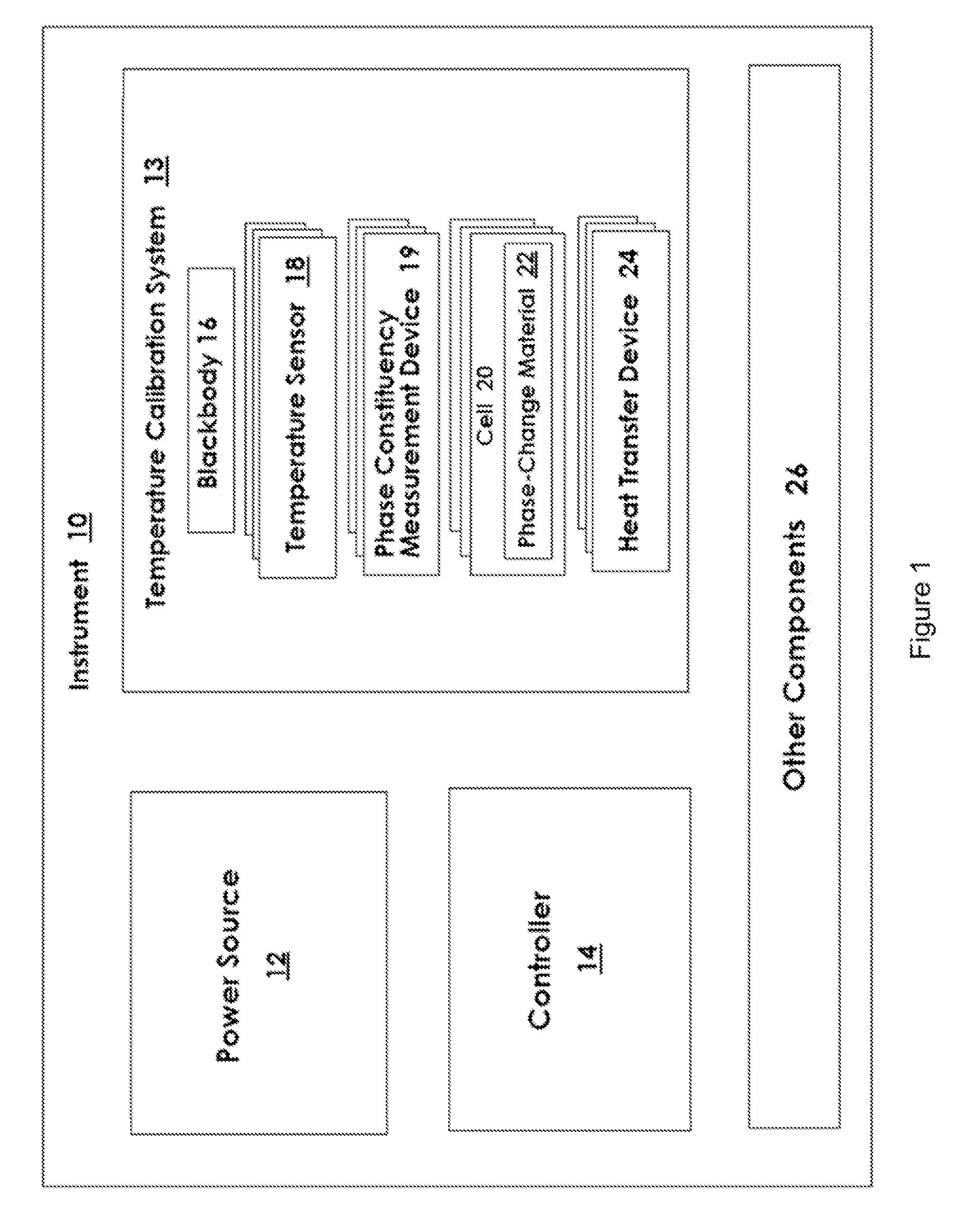
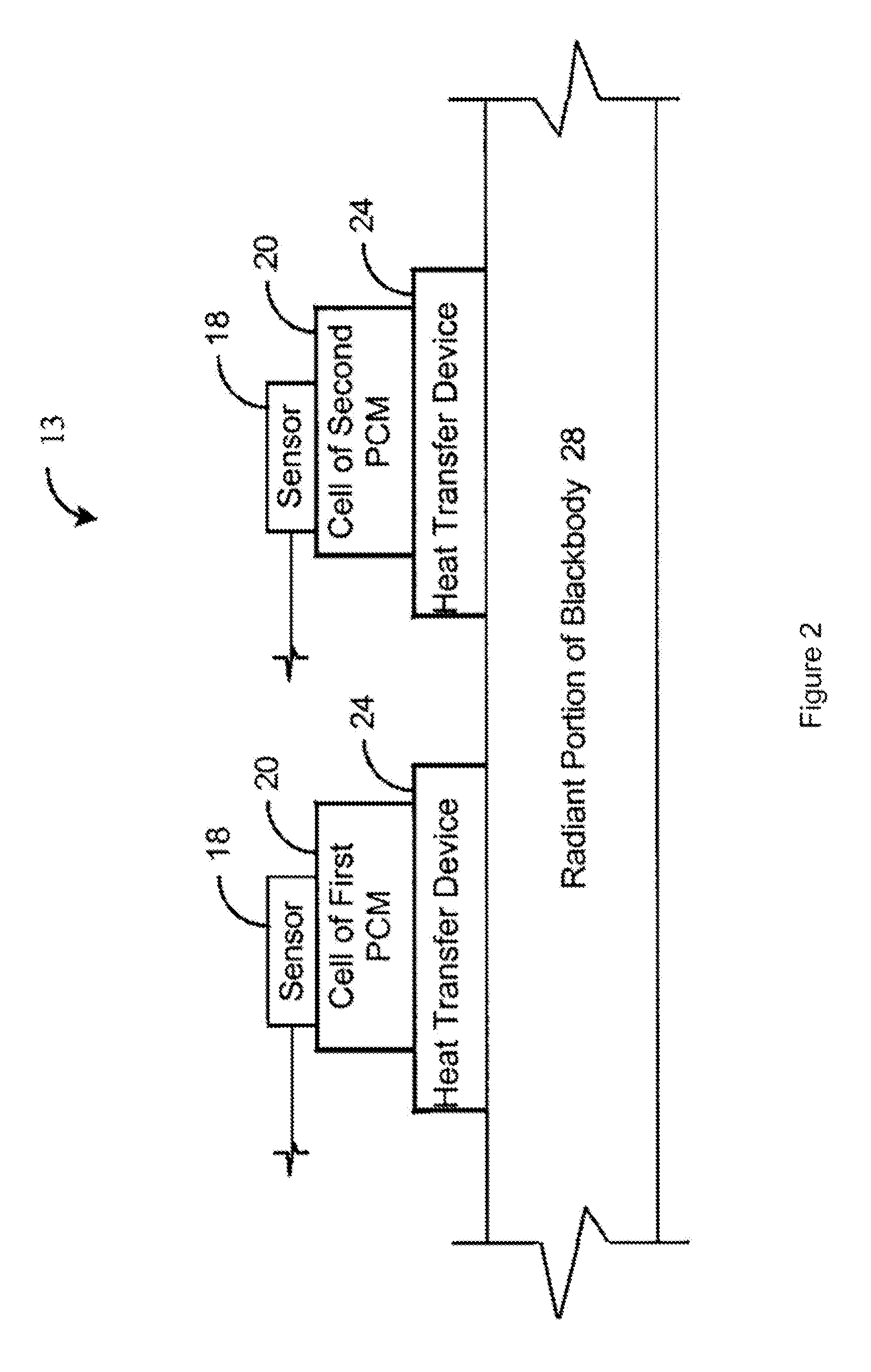
[0029]Referring to FIG. 1, an instrument 10 in accordance with the present invention may include various sub-components as desired or required. For example, an instrument 10 may include a power source 12 for supplying the various components of an instrument 10 with the electrical power they need. Additionally, an instrument 10 may include a controller 14 comprising one or more computers operably connec...


PUM

PropertyMeasurementUnit
melting pointsaaaaaaaaaa
temperaturesaaaaaaaaaa

Abstract

A method for on-orbit calibration of the temperature sensors of a blackbody is disclosed. The method may include selecting a blackbody traveling in a micro-gravity environment and comprising a sensor, a container positioned proximate the sensor and containing a material, and a heat transfer device positioned proximate the at least one container. The heat transfer device may transition the material through a phase change. The temperature sensor may monitor the temperature of the material during the phase change. Additionally, the state of the material may be measured by displacement of the container to improve the accuracy of the plateau temperature measurement. A correction may be calculated to correct any disparity between the temperature reported by the temperature sensor during the phase change and the known plateau temperature, measured at a threshold state of the material, corresponding to that phase change. The correction may be applied to subsequent temperature readings obtained using the temperature sensor.

Description

RELATED APPLICATIONS[0001]This application is a continuation-in-part of co-pending U.S. patent application Ser. No. 12 / 482,622 filed Jun. 11, 2009, entitled “Mini-Cell, On-Orbit, Temperature Re-Calibration Apparatus and Method” which claims the benefit of U.S. Provisional Patent Application Ser. No. 61 / 060,753 filed Jun. 11, 2008, both of which are hereby incorporated by reference.BACKGROUND[0002]1. The Field of the Invention[0003]This invention relates to infrared (IR) instruments and, more particularly, to novel systems and methods for long-term, in-flight calibration of IR instruments.[0004]2. The Background Art[0005]IR instruments must periodically be calibrated in order to provide data of desired or required accuracy. However, the accuracy and stability of temperature sensors used in such calibration procedures can be affected by numerous factors. For example, measurement systems using on-board blackbodies as reference points are subject to temperature sensor drift.[0006]Factor...

Claims


Application Information

Patent Timeline
Patent Type & Authority Applications(United States)
IPC IPC(8): G01K15/00G06F19/00
CPCG01K15/002G01J5/522G01J5/53
Inventor TOPHAM, TROY SHANEBINGHAM, GAIL
Owner UTAH STATE UNIVERSITY
Why Eureka
Try Eureka