Connector

a technology of connecting rods and connecting rods, applied in the direction of coupling device connections, coupling base/cases, securing/insulating coupling contact members, etc., can solve the problem of attenuation of the vibration energy of the wire, and achieve the effect of ensuring the position of the holding hole and the vibration reducing portion

Active Publication Date: 2011-06-16
SUMITOMO WIRING SYST LTD
View PDF7 Cites 13 Cited by
  • Summary
  • Abstract
  • Description
  • Claims
  • Application Information

AI Technical Summary

Benefits of technology

[0009]The electric wire may vibrate. However, the vibration energy of the wire is attenuated due to the integral displacement of the vibration reducing portion and the vibration attenuating member. Part of the attenuated vibration is absorbed by the vibration absorbing portion when the vibrations are transmitted from the vibration reducing portion to the sealing portion. The vibration absorbing portion is outside the holding hole and in front of the holding hole. As a result, the vibration absorbing portion does not directly contact the vibration attenuating member and displacement of the vibration attenuating member is not transmitted directly to the sealing portion. Accordingly, the vibration absorbing portion exhibits a sufficient vibration absorbing function and vibrations transmitted from the electric wire to the terminal fitting are attenuated more effectively.
[0014]Restrictions may be formed on an inner periphery of the holding hole and an outer periphery of the vibration reducing portion to restrict longitudinal displacement of the vibration reducing portion relative to the holding hole by concave-convex fitting. Thus, it is possible to surely position the holding hole and the vibration reducing portion.

Problems solved by technology

However, the vibration energy of the wire is attenuated due to the integral displacement of the vibration reducing portion and the vibration attenuating member.

Method used


Image

  • Connector
  • Connector
  • Connector

Examples


Embodiment Construction

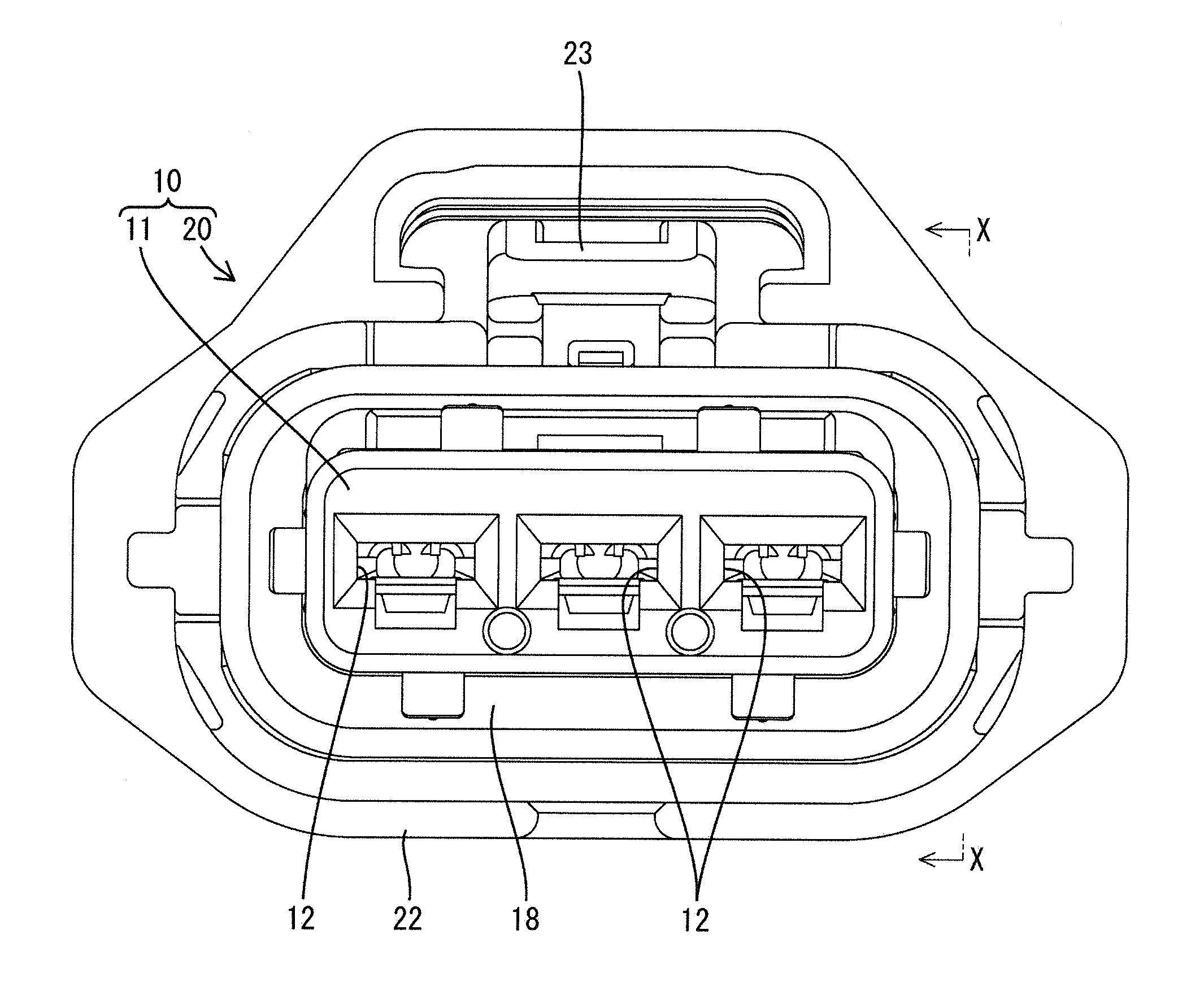
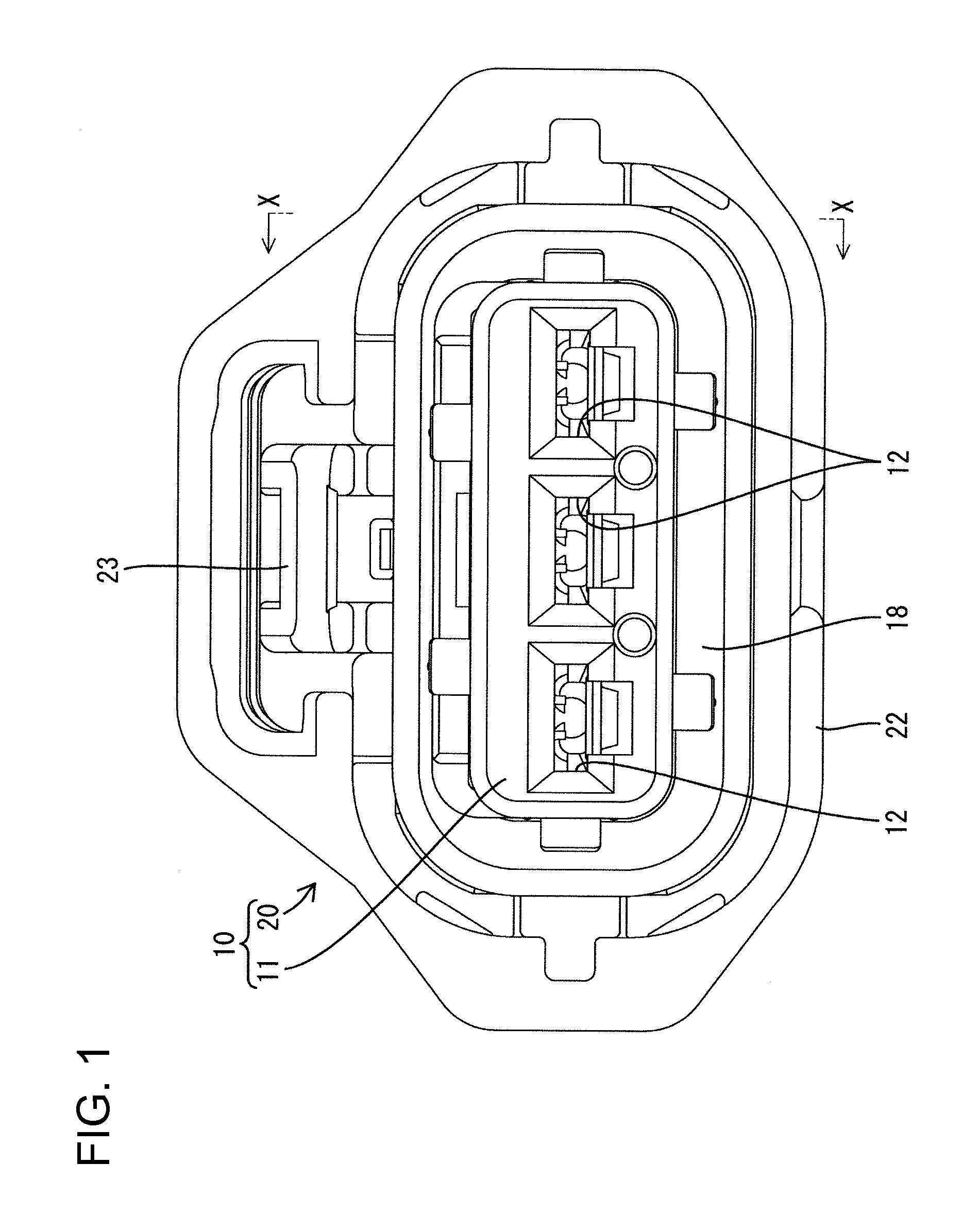
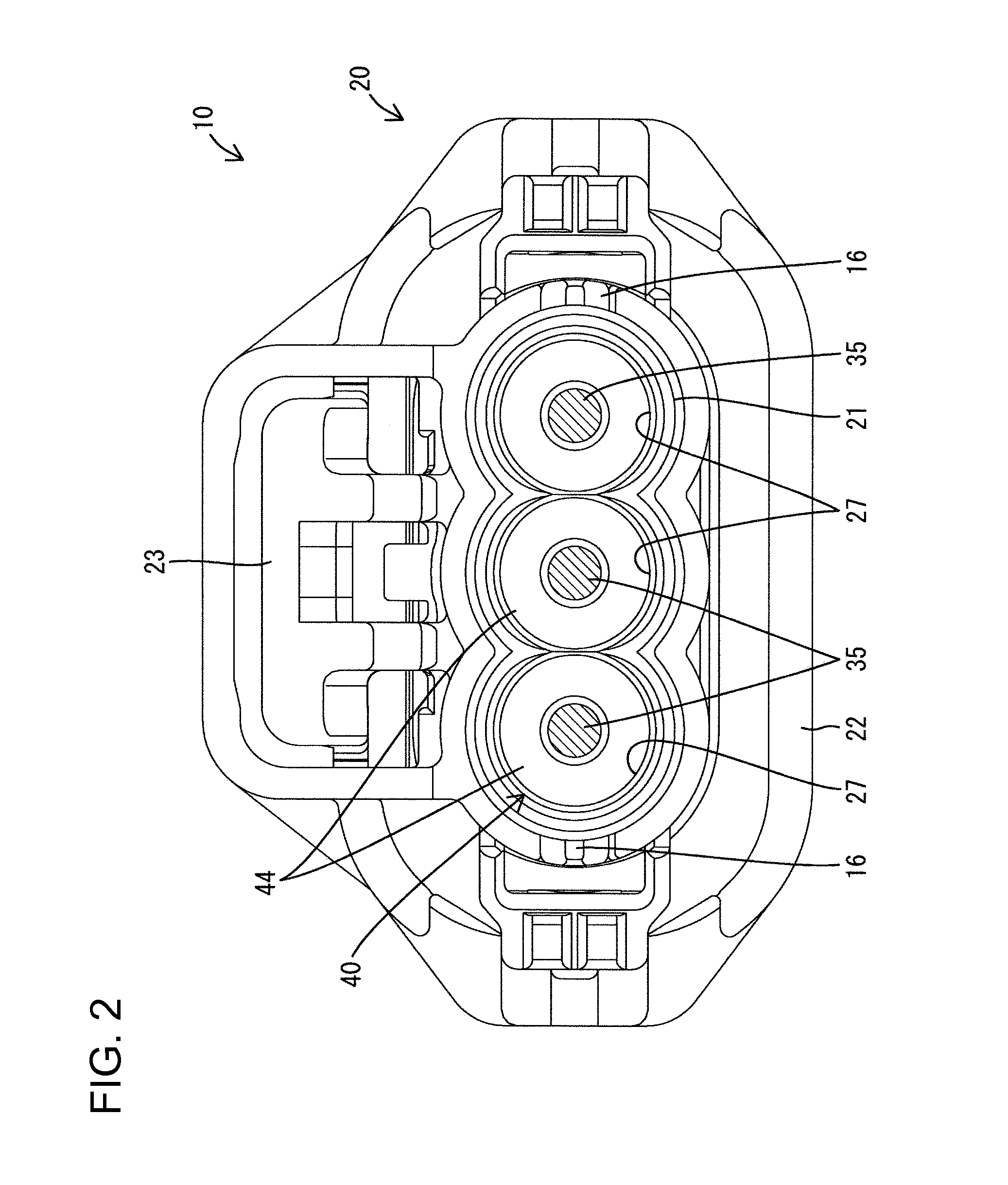
[0024]A connector according to the invention has a housing identified by the numeral 10 in FIGS. 1 to 5. The housing 10 includes a block shaped inner housing 11 that functions as a terminal holding member and an outer housing 20 that functions as a vibration attenuating member. The inner and outer housings 11 and 20 are made of synthetic resin in this embodiment. The connector also includes terminal fittings 30 and rubber plugs 40 that are inserted into the housing 10.

[0025]Cavities 12 penetrate the inner housing 11 in a longitudinal direction and are arranged parallel to each other in a lateral direction. Front portions of the cavities 12 (left side in FIGS. 3 and 4) define terminal housing spaces 13 for housing the terminal fittings 30. Rear portions of the cavities 12 define cylindrical sealing holes 14.

[0026]An outwardly projecting flange 15 is formed continuously around the outer periphery of the inner housing 11 at a position slightly behind the longitudinal center of the inne...


PUM


Abstract

A connector has an inner housing with a cavity for housing a terminal fitting, an outer housing assembled displaceably to the inner housing and a rubber plug. The rubber plug has a sealing portion, a vibration reducing portion and a vibration absorbing portion. The sealing portion is mounted fixedly on a rear end portion of the terminal fitting and is brought into close contact with an inner peripheral surface of the cavity. The vibration reducing portion is fit in a holding hole formed in the outer housing and thus is displaced with the outer housing. The vibration absorbing portion has a smaller thickness than the vibration reducing portion and connects the sealing portion to the vibration reducing portion. The vibration absorbing portion is outside the holding hole and in front of the holding hole.

Description

BACKGROUND OF THE INVENTION[0001]1. Field of the Invention[0002]The invention relates to a connector.[0003]2. Description of the Related Art[0004]JP-A-2009-093896 discloses a connector with a housing that has a terminal holding member. The terminal holding member has a cavity in which a terminal fitting is housed. An electric wire is connected to the terminal fitting and is led out to a position behind the terminal holding member. A vibration attenuating member is assembled to the terminal holding member and is displaceable relative to the terminal holding member in a direction that interests the longitudinal direction of the wire. The vibration attenuating member has a holding hole behind the cavity and the electric wire penetrates through the holding hole. A cylindrical rubber plug is fit on the electric wire and has a sealing portion that is mounted fixedly on a rear end portion of the terminal fitting. The rubber plug is brought hermetically into close contact with an inner peri...

Claims


Application Information

Patent Timeline
Patent Type & Authority Applications(United States)
IPC IPC(8): H01R13/52
CPCH01R13/4361H01R13/5205H01R13/533H01F27/33H01R27/02
Inventor NAKAMURA, HIDETO
Owner SUMITOMO WIRING SYST LTD
Why Eureka
Try Eureka