Method for the designing of tools

a tool and tool design technology, applied in the field of tools design, can solve the problems of addendums difficult to meet the needs of users, etc., and achieve the effect of optimizing the process and avoiding additional processing

Inactive Publication Date: 2011-06-16
NETABTAL MASCHEN
View PDF15 Cites 2 Cited by
  • Summary
  • Abstract
  • Description
  • Claims
  • Application Information

AI Technical Summary

Benefits of technology

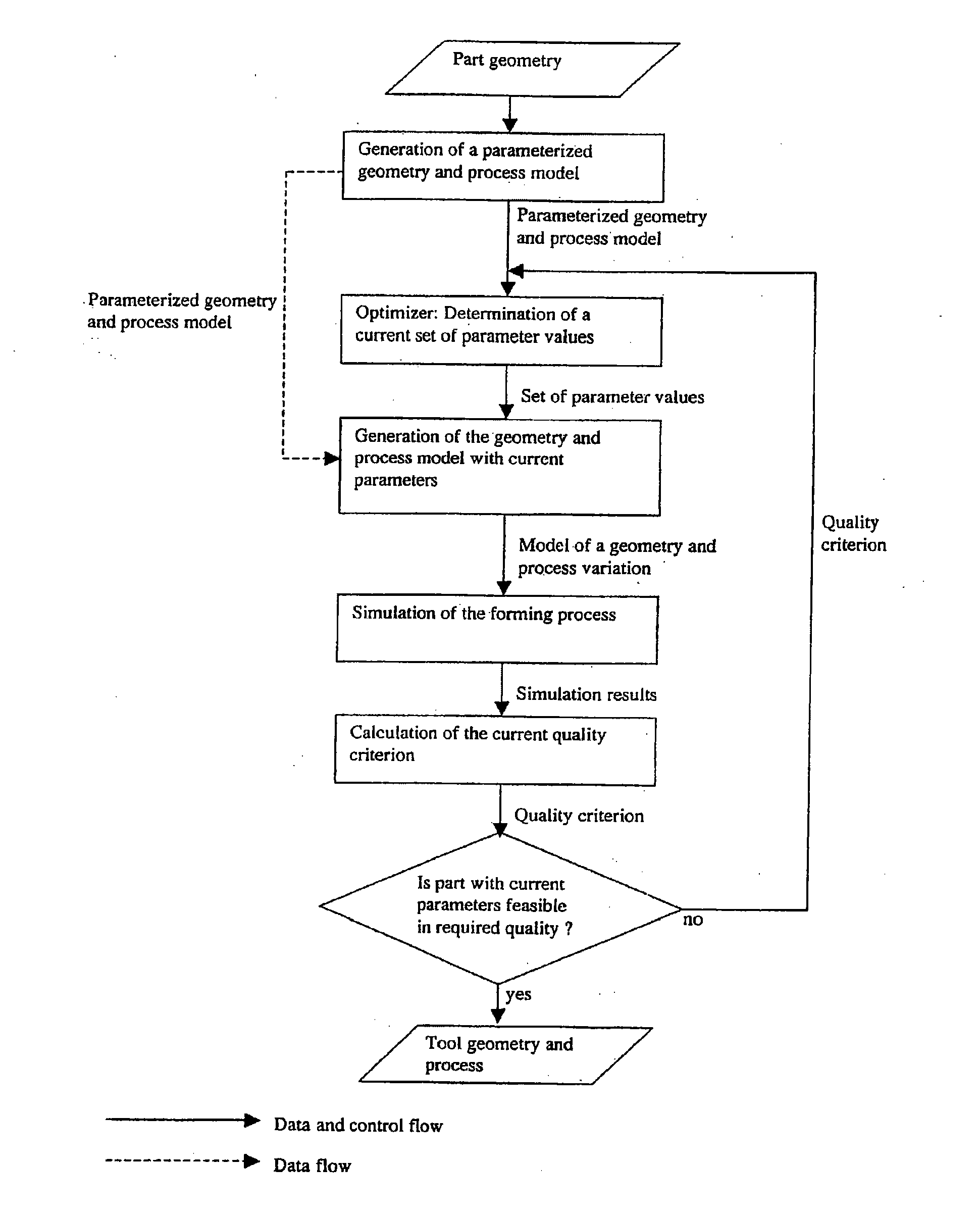
[0009]It is an objective of the present invention to demonstrate a method how addendum surfaces for forming tools can be optimized and created efficiently and easily while avoiding the disadvantages known from prior art.
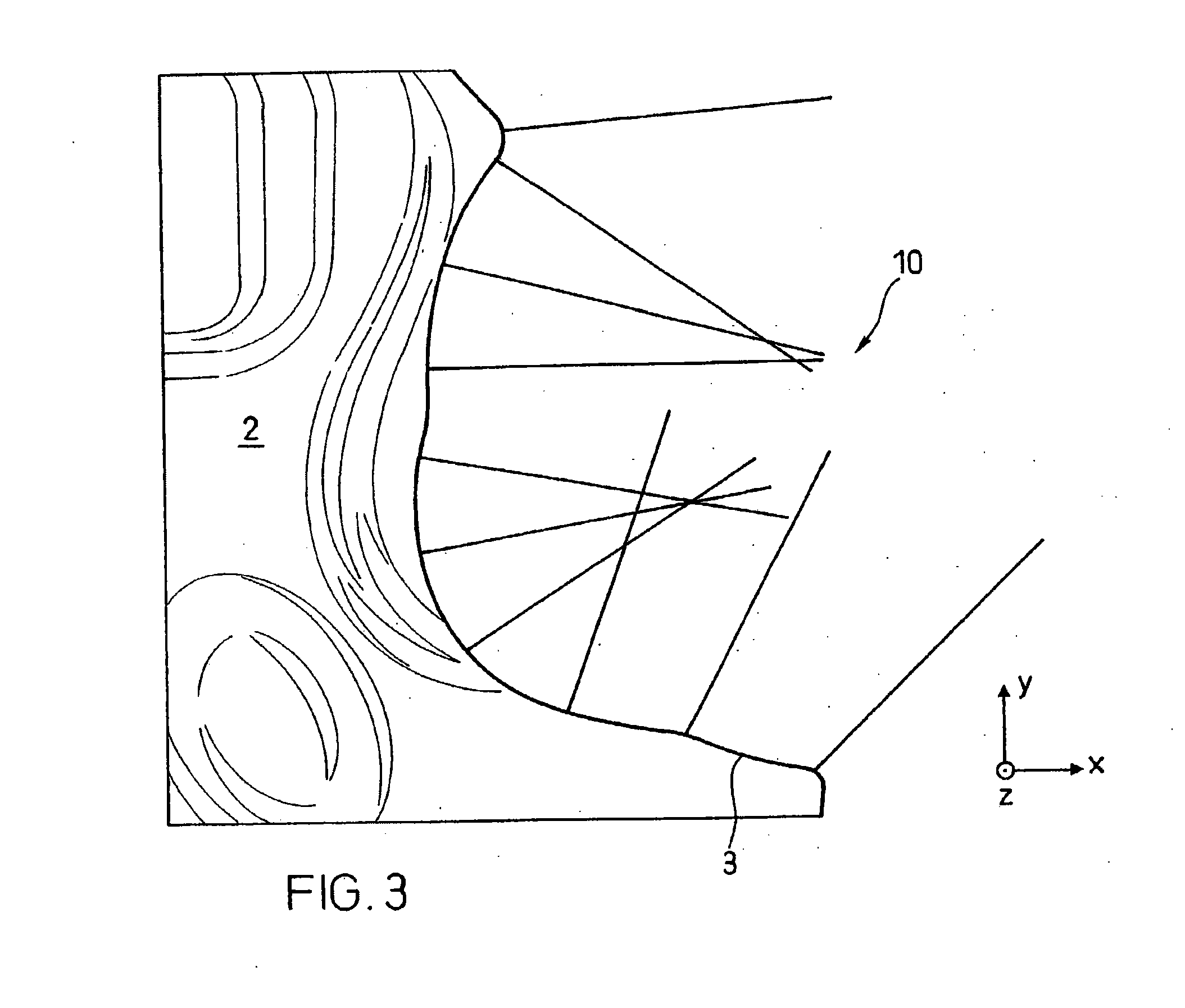
[0016]In the present invention, the initial directions of the sectional profiles on the edge of a component are preferably determined such that they point in the direction of the minimum geometrical change in a defined, fictitious edge zone of the component or in correlation with the flow-direction of the material. Alternative arrangements, such as in concave areas, are possible to avoid negative overlapping. The fictitious edge zone of the component is here notionally formed by a fictitious strip along the edge of the component (resp., the base line), lying in the inside of the component. This edge zone as a rule has a width, which is, for example, approximately 10-times the thickness of the sheet metal. How the direction of the minimum geometry change can be determined is illustrated in FIG. 5. If necessary, adjustments of the initial directions are possible to avoid disadvantageous overlapping of sectional profiles in concave areas.
[0019]The problem field described above is solved preferably as follows in the case of the invention divulged here: The sectional profiles are preferably described by a single type of geometry, (see FIG. 9), which has to be sufficiently general in nature to be able to describe the common sectional profile forms. Sectional profiles arranged next to each other are of corresponding nature making sure that no interpolation errors occur. These sectional profiles are parameterized by forming technology scalar values easy to comprehend by the user (hereinafter referred to as profile parameters), such as, for example, component run-off length, flange length, flange angle, draw bar height, draw bar width, draw bar radius, step height, wall angle, die radius, etc. The sectional profile is then built up based on these profile parameters out of basic elements, for example, circular arcs and line segments, in an automated manner (in this context refer to FIG. 9). In the case of inconsistent profile parameters, these are automatically adapted and optimized in accordance with a defined priority. In this manner, a sectional profile can be predefined exceedingly easily and clearly.
[0022]In the case of the invention divulged here, this problem is solved as follows. Sectional profiles possess characteristic points, which describe the principal course of the sectional profile, Mentioned as examples for such characteristic points shall be a summit of a draw bar, the flank of a step or the control points of a spline, of a Bèzier- or of a NURBS curve. Those characteristic points of every sectional profile corresponding to one another can now be joined together and with this form (continuous) characteristic lines, which extend along an addendum (parallel to a component edge) or at least over sections of it, e.g., the summit line of a draw bar (refer to FIG. 7). The lines defined in this manner are especially suitable for changing the addendum interactively, in that they, for example, are approximated as splines easily variable through control points. Both changes in a vertical direction (i.e., for example, the course of the height of a draw bar) as well as changes in horizontal direction (i.e., for example the horizontal position of the draw bar) can be implemented with this. The change specifically influences the corresponding parameters of the sectional profiles lying in the area of the change and correspondingly the addendum surface. Since a change of a characteristic line in a controlled manner influences several adjacent sectional profiles, such a change is significantly easier to implement than by means of the (manual) changing of individual sectional profiles. If the changing of a profile parameter is to lead to changes of other profile parameters in the adjacent sections (e.g., the changing of the draw bar height shall simultaneously cause a change of the width of the draw bar), then a corresponding working connection can be defined by a coupling matrix. In the case of the method described here, it is also possible to automatically smooth the characteristic lines. With this, geometry jumps at the edge of the component can be easily smoothed (in this context refer to FIG. 18). As smoothing algorithms, for example, one can again utilize uncoiling algorithms, and this both in the horizontal plane as well as in the height.
[0035]If desired, it is possible to use the geometrical information and data related to the tool (die, binder, punch) and the sheet metal part, handled and generated by the herein described invention, as input data for tooling. In this way it is possible to avoid additional processing by a CAD-System, which results in a further optimized process.

Problems solved by technology

In this process the edge areas, in particular the addendums, represent problematic zones.
The dimensioning and adjustment of the addendums represents a great problem field today.
Frequently, this is an iterative process, which is associated with a lot of rejected parts and a substantial consumption of energy and other utilities.
The production of addendums today, to a great extent, takes place manually by means of computer-aided design systems (CAD) and takes a lot of time.
Already solely the establishment of an addendum for a large body part can, as a result, easily take several weeks.
The known sectional profiles are different to link, resulting in bad interpolation data for addendum surfaces.
For most tools, in addition, a limited number of such sectional profile types are sufficient.
This method is not convincing.
The resulting addendum surfaces are still problematic due to insufficient results from interpolation.
This procedure, however, has the following serious disadvantages and problems.
On the one hand, the smoothing of the edge of the component represents a major problem.
If now the same sectional profile throughout is applied to this edge, then these indentations, etc. continue into the addendum, which can lead to an extremely irregular addendum surface.
Both solutions require a lot of time and lead to the result that no usable addendum can be produced fully automatically.
The latter fact is a disadvantage, particularly if one would like to automatically design, resp., optimize the addendum via an optimization loop in conjunction with a forming simulation code and a quality criterion.
On the other hand, the sectional profile direction is difficult to determine automatically.
In applying the directions vertical to the edge of the component projected in the drawing direction, at concave points overlaps of the sectional profiles result, which makes the creation of the addendum surface impossible.

Method used


Image

  • Method for the designing of tools
  • Method for the designing of tools
  • Method for the designing of tools

Examples


Embodiment Construction

[0050]FIG. 1 illustrates essential elements of a forming tool 1. Identifiable are a component 2, a component edge 3, an addendum 4, a punch opening line 5 and a binder surface 6.

[0051]FIG. 2 shows a component 2 with an irregular component edge 3. The irregularities in the course of the edge of the component 3 are filled in with fill surfaces 7 and smoothed. Fill surfaces have to merge C1-continuous (values of the first differentiation identical on both sides) into the geometry of the component 2. Such surfaces 7 can, for example, be generated through geometrical approximations under C1-boundary condition on the edge of the component 3, or through a finite element shell solution with C1-boundary condition. The fill surfaces 7 resulting in this manner are smoothed and continuous and complement the component 2 in an optimum manner. In the zone of a fill surface 7, alternatively an edge 8 of the fill surface 7 is decisive for the course of the sectional profiles.

[0052]FIG. 3 illustrates...


PUM


Abstract

The invention concerns a method for the creation of addendums (4) of tools for sheet metal formed parts (2). In the case of this method, fill surfaces (7) for the smoothing of irregular zones of a component edge (3) are generated. Initial directions (31) of sectional profiles (10) are determined in such a manner, that sectional profiles (10) at a distance from one another are arranged along a component (3, 8) with utilization of these initial directions (31) and that an addendum (4) is creatable by the connection of these sectional profiles (10).

Description

CROSS REFERENCE TO RELATED APPLICATION[0001]This application is a continuation of co-pending application Serial No. 10 / 275,633, filed on 21 Apr. 2003. The co-pending parent application is hereby incorporated by reference herein and is made a part hereof, including but not limited to those portions which specifically appear hereinafter.[0002]1. Field of the Invention[0003]The invention presented here lies in the field of the designing of addendum zones of tools for the manufacture of formed sheet metal parts (deep-drawing / stretch-forming processes) and their optimization.[0004]2. Discussion of Related Art[0005]Formed sheet metal parts as a rule are manufactured by deep-drawing. The semi-finished parts, the so-called sheet metal blanks (blank), for this purpose are placed in multi-part forming tools. By means of presses, in which the forming tools are clamped, the parts are formed. The parts, as a rule, are manufactured out of a flat sheet metal blank in several forming steps (drawing...

Claims


Application Information

Patent Timeline
Patent Type & Authority Applications(United States)
IPC IPC(8): G06F17/50G05B19/4099
CPCG05B19/4099G05B2219/49007G05B2219/35533Y02P90/02
Inventor HILLMANN, MATTHIASKUBLI, WALDEMAR
Owner NETABTAL MASCHEN
Why Eureka
Try Eureka