
Industrial gripper with multiple degrees of freedom

a technology of industrial grippers and freedom, applied in the direction of gripping heads, load-engaging elements, thin material handling, etc., can solve the problems of difficult to improve productivity and operation efficiency in industrial fields, limited product shape of industrial grippers, and inability to stably grip products

Active Publication Date: 2011-06-23
SAMSUNG ELECTRONICS CO LTD
View PDF6 Cites 65 Cited by
  • Summary
  • Abstract
  • Description
  • Claims
  • Application Information

AI Technical Summary

Benefits of technology

[0029]In accordance with another aspect, an industrial gripper with multiple degrees of freedom includes a base plate, three finger units to be moved relative to the base plate, a supporting frame to support the finger units coupled thereto, a first drive unit coupled to the supporting frame to allow simultaneous angular displacement of the finger units, and a second drive unit coupled to the supporting frame to adjust orientation angles between

Problems solved by technology

Therefore, the shape of products that may be gripped by industrial grippers is limited.
Even if it is attempted to grip complicated shapes of products, stably gripping the products may be impossible due to structural constraints.
In conclusion, the above described limit in the shape of products to be gripped by industrial grippers may make it difficult to improve productivity and operation efficiency in industrial fields that may need to deal with multiple kinds of products.
Although robot hands similar to human hands have been developed, use of the robot hands entails significant cost burdens, and it may be difficult to apply robot hands to actual industrial fields in consideration of workability and reliability.
When it is attempted to grip an object in an industrial field by use of robot hands similar to human hands, the robot hands may clasp the object similar to action of human hands, but may fail to grip an accurate grip position of the object so that a specific portion of the object is exposed.

Method used


Image

  • Industrial gripper with multiple degrees of freedom
  • Industrial gripper with multiple degrees of freedom
  • Industrial gripper with multiple degrees of freedom

Examples


Embodiment Construction

[0037]Reference will now be made in detail to the embodiments, examples of which are illustrated in the accompanying drawings, wherein like reference numerals refer to like elements throughout.

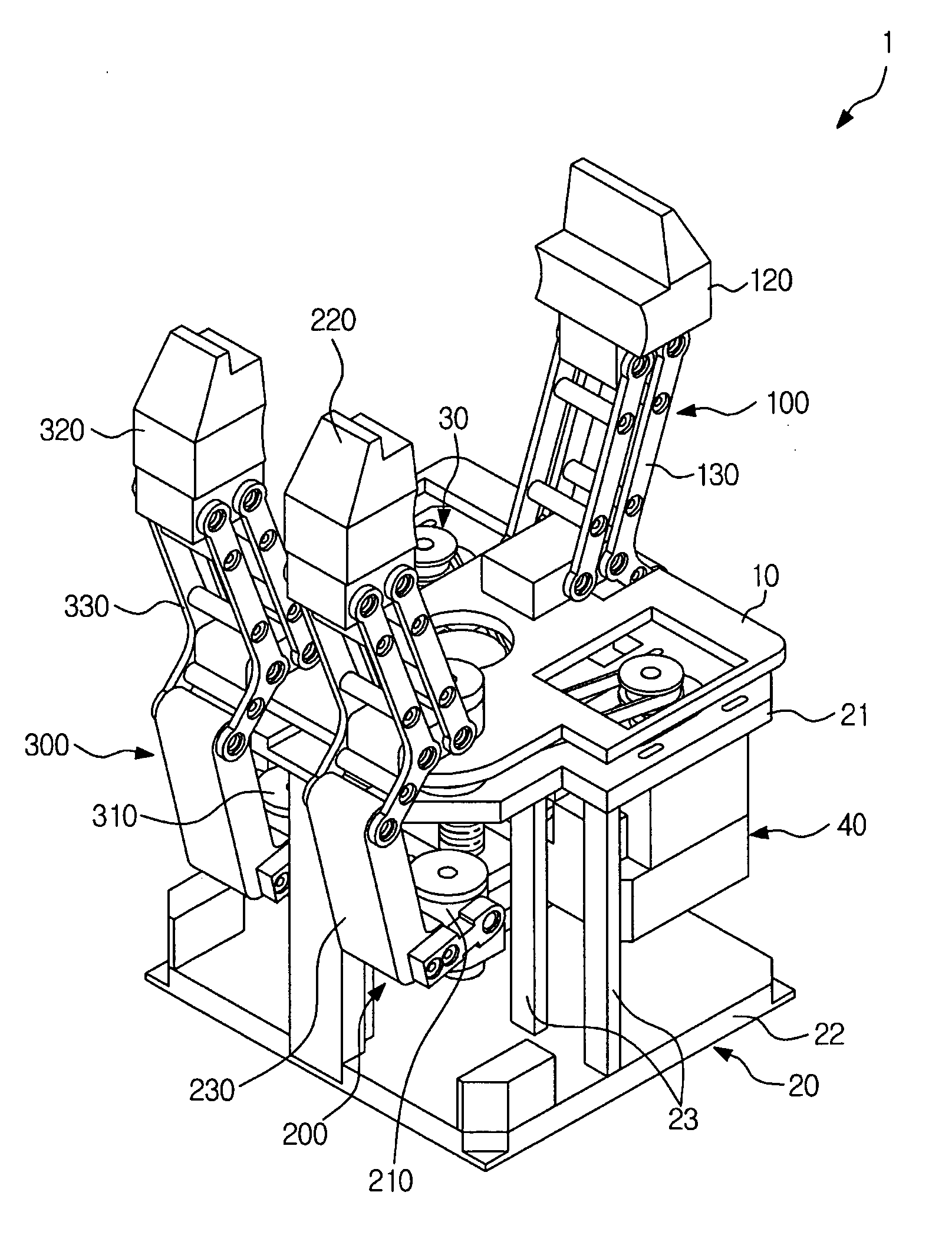
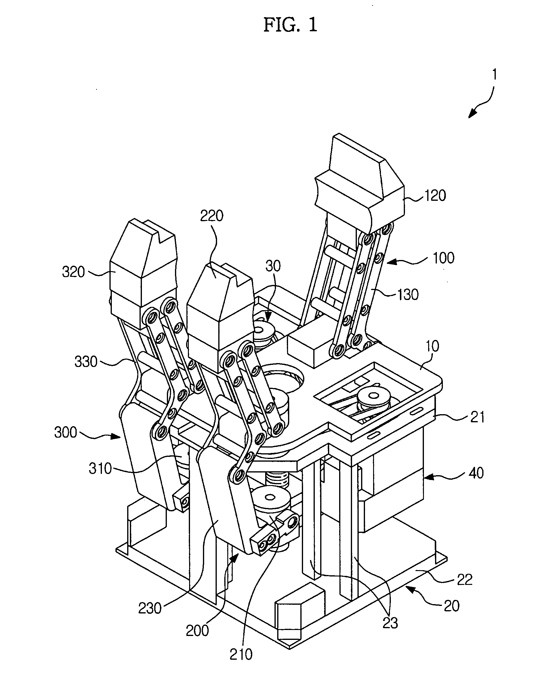
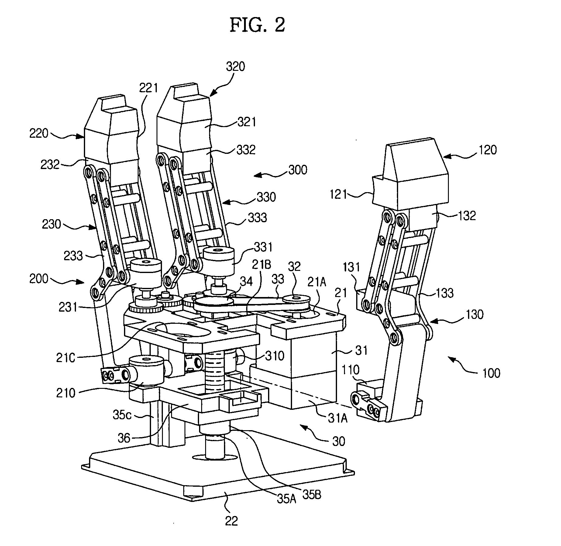
[0038]FIG. 1 is a perspective view illustrating an industrial gripper with multiple degrees of freedom according to an embodiment, and FIG. 2 is a perspective view illustrating a state in which a finger unit is separated from the industrial gripper with multiple degrees of freedom illustrated in FIG. 1.

[0039]As illustrated in FIGS. 1 and 2, the industrial gripper 1 with multiple degrees of freedom according to the embodiment includes a base plate 10, a plurality of finger units 100, 200 and 300 to be moved respectively relative to the base plate 10, a supporting unit 20 to support the plurality of finger units 100, 200 and 300 to allow the plurality of finger units 100, 200 and 300 to be moved relative to the base plate 10, a first drive unit 30 to cause angular displacement of the plurality o...


PUM


Abstract

An industrial gripper includes a base plate, at least three finger units to be moved relative to the base plate, a supporting unit to support the finger units, a first drive unit coupled to the supporting unit to allow simultaneous angular displacement of the finger units toward an object, and a second drive unit coupled to the supporting unit to adjust orientation angles between the finger units. Each of the finger units includes an intermediation member to be moved in a first direction by the first drive unit, a grip member to grip the object by being moved in a second direction different from the first direction as a movement direction of the intermediation member, and a connection member to convert the first direction movement of the intermediation member into the second direction movement of the grip member.

Description

CROSS-REFERENCE TO RELATED APPLICATIONS[0001]This application claims the benefit of Korean Patent Application No. 2009-0128151, filed on Dec. 21, 2009 in the Korean Intellectual Property Office, the disclosure of which is incorporated herein by reference.BACKGROUND[0002]1. Field[0003]Embodiments relate to an industrial gripper with multiple degrees of freedom to stably grip products with various shapes and strengths in response to diversity of products used in industrial fields.[0004]2. Description of the Related Art[0005]Recently, as the lifespan and use period of products decrease and the diversity of demands of customers who use the products increases, there is an increasing need for production methods to flexibly deal with multiple kinds of products, differently from the conventional mass-production of one kind of product.[0006]Accordingly, a variety of equipment used in industrial fields may need flexibility to deal with multiple kinds of products.[0007]Industrial grippers have...

Claims


Application Information

Patent Timeline
IPC IPC(8): B25J15/10
CPCB25J15/10B25J15/0266B25J15/0009B25J15/0253Y10S294/902
Inventor PARK, HAHNJUNG, SUNG WOOKHWANG, JAE CHULCHOI, YONG WON
Owner SAMSUNG ELECTRONICS CO LTD
Learn More