
Adjustable protective apparel

a protective clothing and adjustable technology, applied in protective clothing, mechanical equipment, cables, etc., can solve the problems of releasing the tension in the line and no way to inhibit the line from unwinding from the first spool

Inactive Publication Date: 2011-07-14
ENVENTYS
View PDF30 Cites 98 Cited by
  • Summary
  • Abstract
  • Description
  • Claims
  • Application Information

AI Technical Summary

Benefits of technology

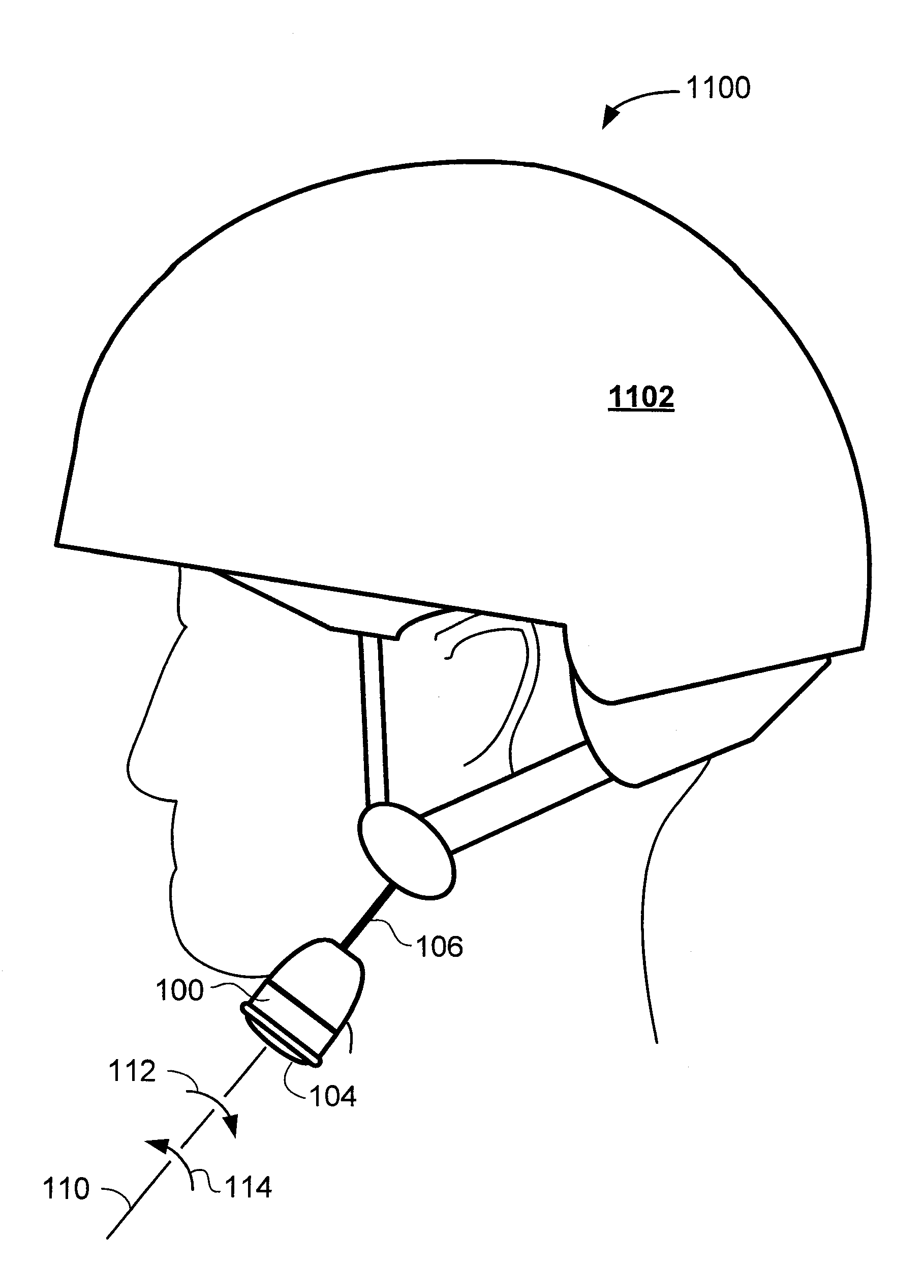
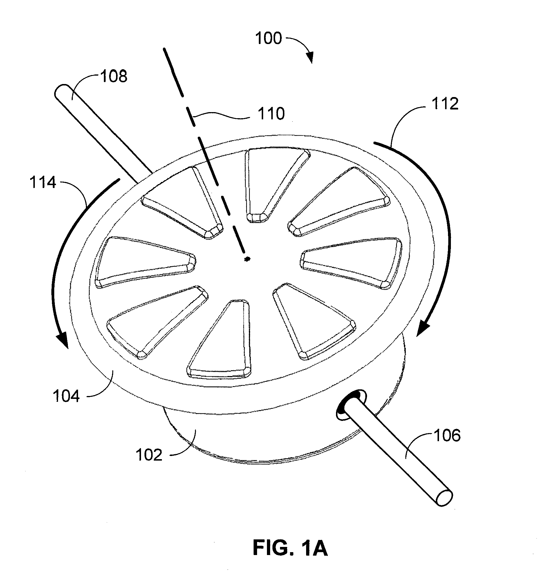
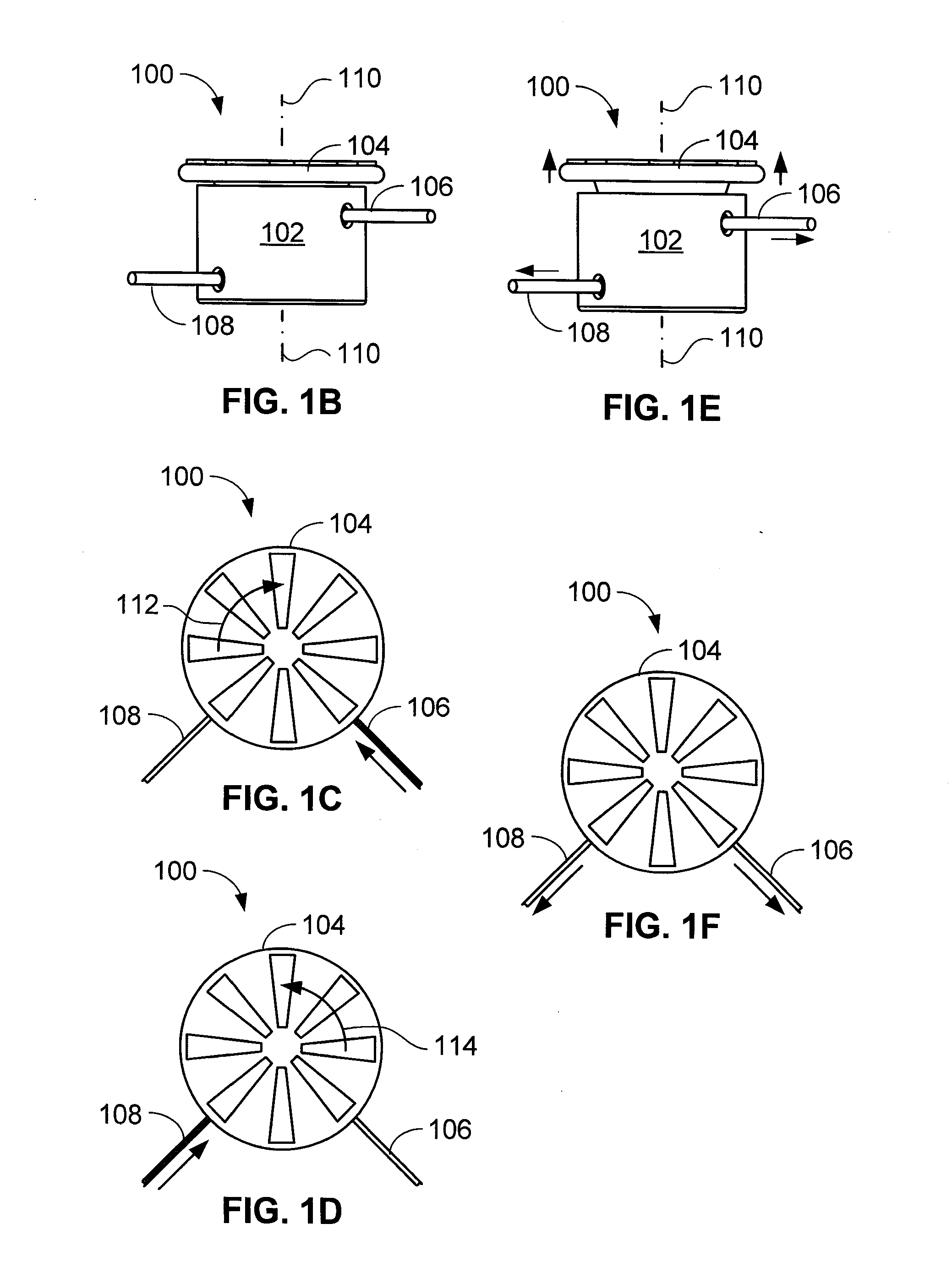
[0014]Accordingly, one aspect of the present invention relates to an article of protective apparel for placement on and protection of a portion of the body of a user of the article. The article includes a protective shell and a bi-directional device that receives a first and second line that each extend to the shell. Rotation of a control handle that extends from the bi-directional device causes portions of the lines to be drawn into the device, thereby tightening the protective shell about the user.
[0018]Yet another aspect of the invention relates to a helmet having first and second shell portions. When a control handle of the helmet is rotated, the first shell portion is drawn toward the second shell portion thereby tightening the helmet about the head of the user.

Problems solved by technology

Unfortunately, prior art two-spool combinations having only a single dial, crank or the like are generally intended to be used with only a single line and thus have no need to 1) use a single dial to wind the spools independently of each other, and / or 2) inhibit the rotation of a first spool, thereby preventing the first line from being unwound, when winding the second line on the second spool.
Unfortunately, rotation of the dial in the opposite direction does not cause either spool to wind the line; instead, in conjunction with its intended purpose, rotating the dial in this opposite direction causes both spools to unwind, thereby releasing the tension in the line.
Unfortunately, the spools in Canney are inseparably coupled together such that rotation of one necessarily causes rotation of the other.
Thus, although rotation of the handle in Canney in a first direction causes the line to wind around the first spool and rotation of the handle in a second (opposite) direction causes the other end of the line wind around the second spool, there is no way to inhibit the line from unwinding from the first spool when the line is being wound around the second spool.

Method used


Image

  • Adjustable protective apparel
  • Adjustable protective apparel
  • Adjustable protective apparel

Examples


Embodiment Construction

[0056]As a preliminary matter, it will readily be understood by one having ordinary skill in the relevant art (“Ordinary Artisan”) that the present invention has broad utility and application. Furthermore, any embodiment discussed and identified as being “preferred” is considered to be part of a best mode contemplated for carrying out the present invention. Other embodiments also may be discussed for additional illustrative purposes in providing a full and enabling disclosure of the present invention. Moreover, many embodiments, such as adaptations, variations, modifications, and equivalent arrangements, will be implicitly disclosed by the embodiments described herein and fall within the scope of the present invention.

[0057]Accordingly, while the present invention is described herein in detail in relation to one or more embodiments, it is to be understood that this disclosure is illustrative and exemplary of the present invention, and is made merely for the purposes of providing a f...


PUM


Abstract

An article of protective apparel for placement on and protection of a portion of the body of a user includes a protective shell and bi-directional device that receives a first and second line that each extend to the shell. Rotation of a control handle of the bi-directional device causes portions of the lines to be drawn into the device, thereby tightening the protective shell about the user. Optionally, the article is a helmet for having an adjustable chin strap that is capable of being tightened by manual rotation of the control handle of the device. Optionally, the article of protective apparel is capable of being loosened by manual positioning of the control handle into a release position.

Description

CROSS-REFERENCE TO RELATED APPLICATION[0001]This application is a continuation-in-part of, and claims priority under 35 U.S.C. §120 to, U.S. patent application Ser. No. 11 / 276,400, filed Feb. 27, 2006, which is a nonprovisional of, and claims priority under 35 U.S.C. §119(e) to, U.S. Provisional Patent Application No. 60 / 656,335, filed Feb. 25, 2005, and which '400 application is a continuation-in-part of:[0002](1) U.S. patent application Ser. No. 11 / 276,357, filed Feb. 24, 2006, which published as U.S. Patent Application Publication No. US 2006 / 0185357, and which '357 application is a nonprovisional of 60 / 656,335, and further which '357 application is a continuation-in-part of U.S. patent application Ser. No. 11 / 222,549, filed Sep. 9, 2005, which '549 application is a nonprovisional of 60 / 656,335 and U.S. Provisional Patent Application No. 60 / 608,397, and which '549 application a continuation-in-part of each of:[0003](A) U.S. patent application Ser. No. 11 / 123,900 filed May 6, 2005...

Claims


Application Information

Patent Timeline
IPC IPC(8): A42B1/22
CPCA41D1/04A41F1/008A42B3/145F41H1/04F16G11/14F41H1/02F16G11/12
Inventor KOVACEVICH, IAN D.DAHLQUIST, KEVIN J.PHILPOTT, TOMBIZZELL, DANIEL LEE
Owner ENVENTYS
Learn More