Collision mitigation system

a technology of collision mitigation and frame assembly, which is applied in the field of vehicles, can solve the problems of increased momentum that these vehicles must absorb, sudden change of momentum, and severe injury to the vehicle occupants

Inactive Publication Date: 2011-07-14
HONDA MOTOR CO LTD
View PDF31 Cites 18 Cited by
  • Summary
  • Abstract
  • Description
  • Claims
  • Application Information

AI Technical Summary

Problems solved by technology

Unfortunately, the smaller vehicle tends to move backward after these crashes, which increases the amount of momentum that these vehicles must absorb.
Unfortunately, one of the leading causes of injury and death in this type of collision is the sudden change in momentum.
This sudden change in momentum can cause severe injury to the vehicle occupant.

Method used


Image

  • Collision mitigation system
  • Collision mitigation system
  • Collision mitigation system

Examples


Embodiment Construction

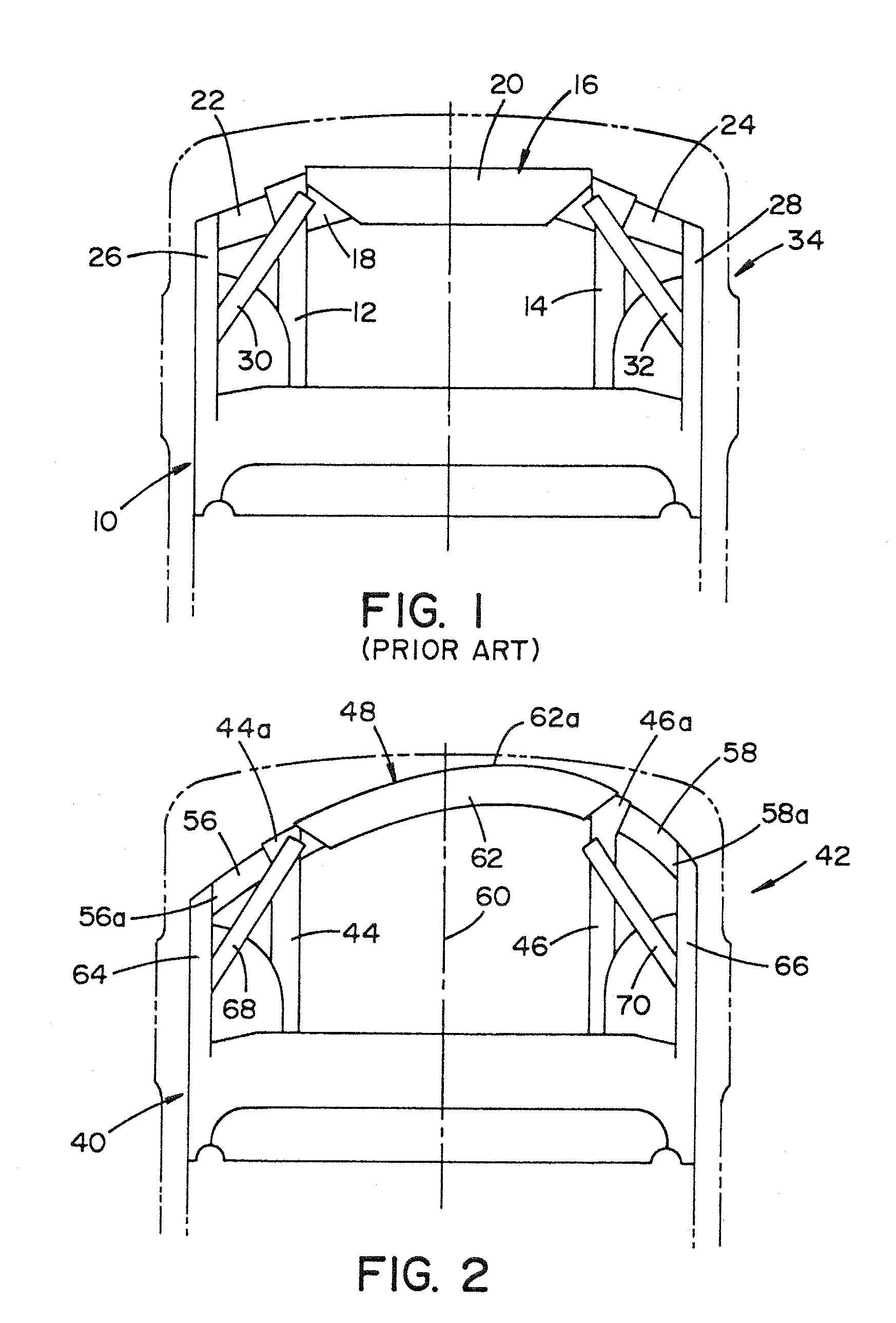
[0013]Referring now to the drawings, wherein the showings are for purposes of illustrating one or more exemplary embodiments and not for purposes of limiting same, FIG. 1 illustrates a prior art frame assembly 10 for a vehicle 34. In particular, the illustrated frame assembly 10 is a front frame assembly including a pair of spaced apart side frame members 12, 14 extended longitudinally along opposite sides of the vehicle 34 and a bumper beam 16 extended between forward end portions of the frame members 12, 14. The illustrated bumper beam 16 of the prior art frame assembly 10 has a symmetrical profile along its longitudinal length.

[0014]In particular, the bumper beam 16 includes a center portion 18 spanning between the frame members 12, 14. A reinforcing structure or bulkhead 20 can be secured to the center portion 18 as shown. The bumper beam 16 can further include lateral portions 22, 24 flanking the center portion 18. Specifically, the first lateral portion 22 can extend laterally...


PUM


Abstract

A collision mitigation system for a vehicle has a frame assembly including a pair of frame members extending longitudinally along opposite lateral sides of a vehicle. A bumper beam extends across forward end portions of the pair of frame members. The bumper beam has a curved asymmetrical profile for guiding movement of the vehicle during a front-end offset crash event.

Description

BACKGROUND[0001]Exemplary embodiments herein relate to vehicles, and more particularly to a collision mitigation system and frame assembly.[0002]For handling car-to-car frontal offset collisions, most current vehicles are designed such that the vehicle safety cage absorbs as much momentum as possible over the longest possible time span without allowing anything to intrude into the passenger cabin. This design methodology typically favors larger, heavier vehicles, as they tend to continue forward after colliding with smaller vehicles. This reduces the amount of momentum that must be absorbed. Unfortunately, the smaller vehicle tends to move backward after these crashes, which increases the amount of momentum that these vehicles must absorb.[0003]By way of example, a small vehicle can go from 40 mph to −5 mph in a very short period of time after a frontal offset collision, while a larger vehicle can go from 40 mph to 5 mph in a slightly longer span due to the length of the front-end c...

Claims


Application Information

Patent Timeline
Patent Type & Authority Applications(United States)
IPC IPC(8): G08G1/16B60R19/24B62D6/00
CPCB60R19/40B62D15/0265B60R19/54
Inventor SCHRADER, MICHAEL A.
Owner HONDA MOTOR CO LTD
Why Eureka
Try Eureka