
Recumbant Style Powered Unicycle

Active Publication Date: 2011-07-21
CHEN SHANE
View PDF18 Cites 20 Cited by
  • Summary
  • Abstract
  • Description
  • Claims
  • Application Information

AI Technical Summary

Problems solved by technology

This type of turning is disadvantageously unfamiliar and difficult to most people compared to more familiar techniques.
A result of this smaller radius is a turning experience that involves undesired turning or spinning of a user, left and right, as they attempt to turn.
The problem is exacerbated with the multiple turning moves needed to fine tune a turn.

Method used


Image

  • Recumbant Style Powered Unicycle
  • Recumbant Style Powered Unicycle
  • Recumbant Style Powered Unicycle

Examples


Embodiment Construction

taken together with the drawings.

BRIEF DESCRIPTION OF THE DRAWINGS

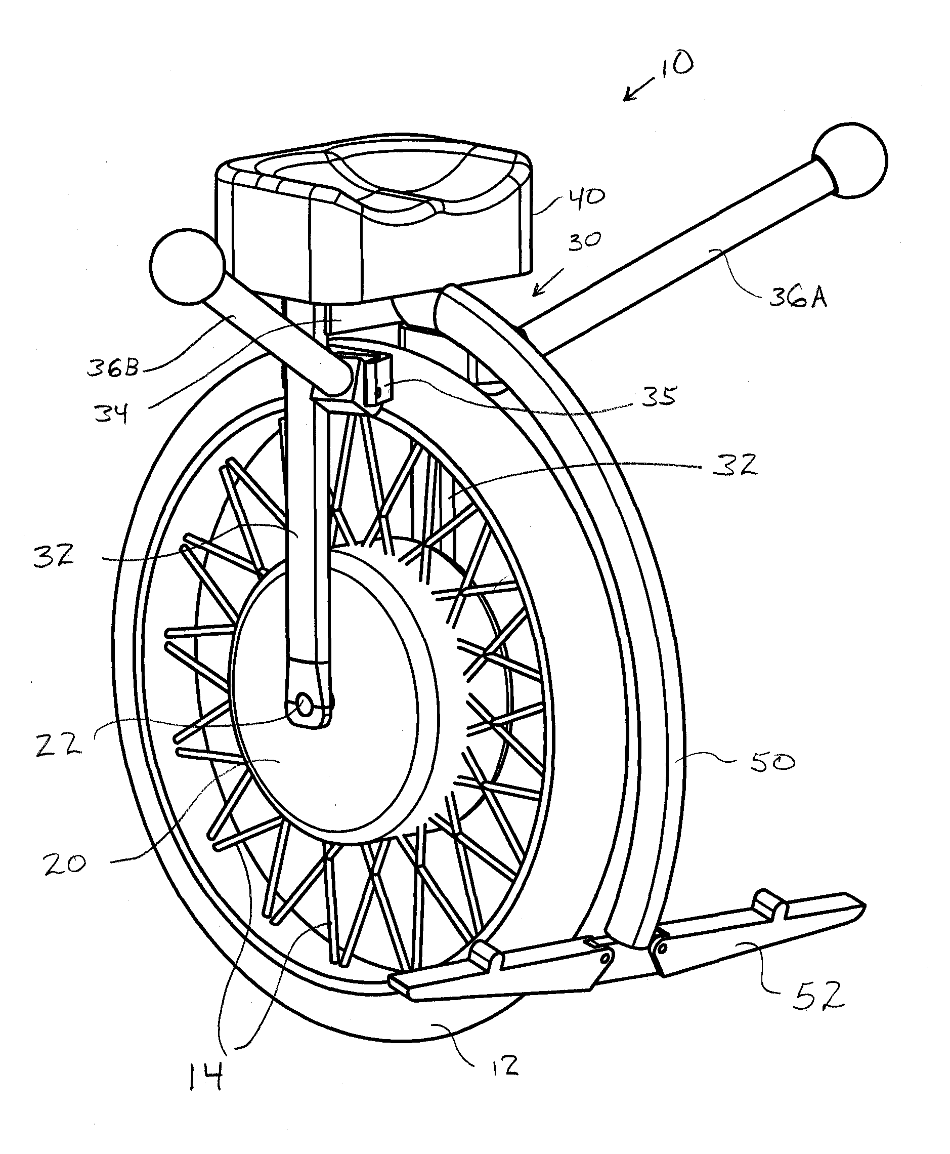
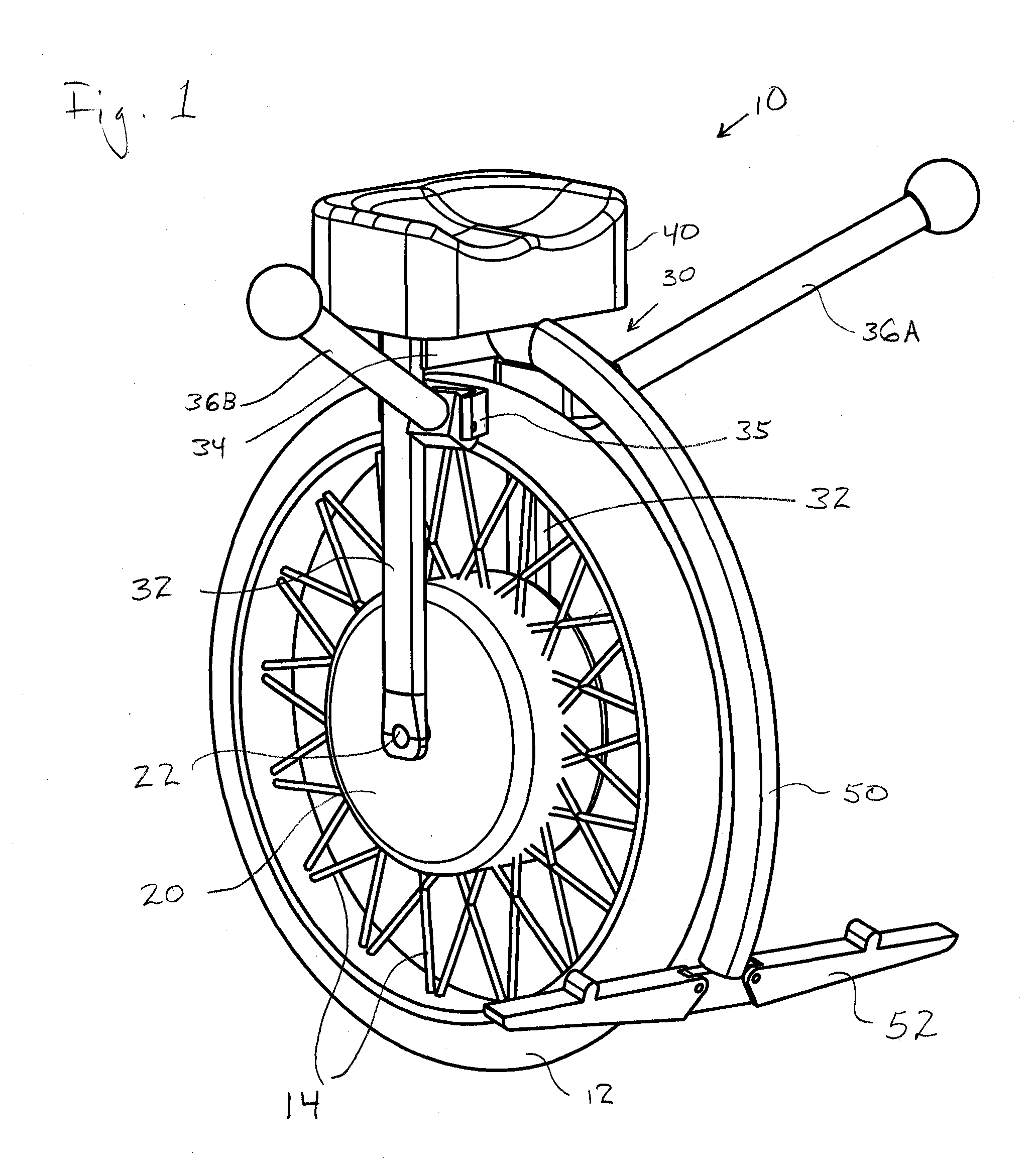
[0013]FIG. 1 is a perspective view of an embodiment of a powered unicycle in accordance with the present invention.

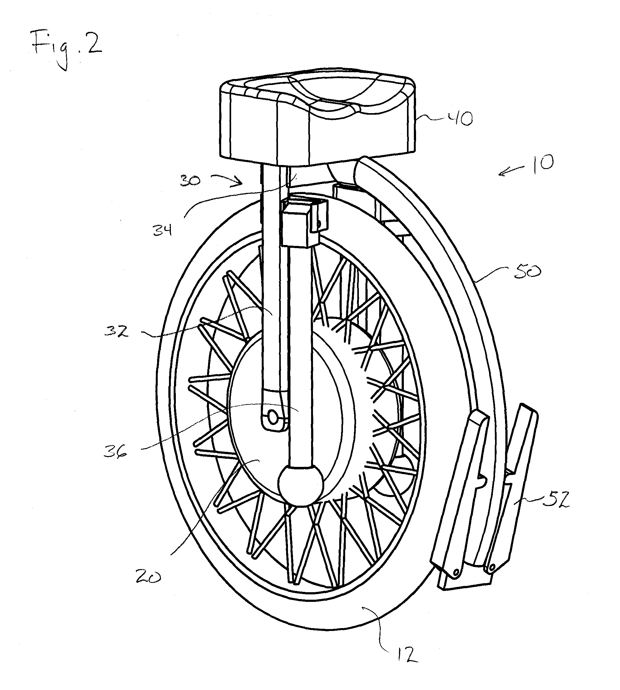
[0014]FIG. 2 is a perspective view of the powered unicycle of FIG. 1 with steering handles and foot supports in folded position.

[0015]FIG. 3 is a top plan view of the powered unicycle of FIG. 1 with the seat and leg extension pivoted to the left, as during a right turn.

[0016]FIG. 4 is a perspective view of another embodiment of a powered unicycle in accordance with the present invention.

[0017]FIG. 5 is a perspective view of the powered unicycle of FIG. 4 with lines included to illustrate the geometry of the shifting seat.

DETAILED DESCRIPTION

[0018]Referring to FIG. 1, a perspective view of a powered unicycle 10 in accordance with the present invention is shown. Unicycle 10 may include a wheel 10, coupled through spokes or other members 12, to a hub 20. The hub preferably has an axle 22 that is coupled on b...


PUM


Abstract

A powered unicycle device having a single wheel, a wheel support frame and a seat mounted above the wheel. The unicycle may have laterally extending control members that provide both steering and desired resistance during turning. A foot support member or members may extend forward of the wheel's axle and be spaced from the axle to provide desired resistance during turning. The seat may be movably mounted to a track and that track may be curved. Various embodiments are disclosed.

Description

CROSS REFERENCE TO RELATED APPLICATION(S)[0001]This application claims the benefit of U.S. Provisional Application No. 61 / 295,730, filed Jan. 17, 2010, and having the same title and inventor(s) as above.FIELD OF THE INVENTION[0002]The present invention relates to unicycles and, more specifically, powered unicycles.BACKGROUND OF THE INVENTION[0003]Unicycles are known in the art and include pedal-operated and powered devices. Powered unicycles include those disclosed in U.S. Pat. No. 6,302,230 issued to Kamen et al. for Personal Mobility Vehicles and Methods (the '230 patent) and U.S. patent application Ser. No. 10 / 569,152 filed by Alexander for a Powered Unicycle (the '152 application). The '230 patent includes two-wheel and one-wheel embodiments, the two-wheel embodiment including the “Segway”, a highly-publicized personal transport device having a user platform between (or above) two parallel wheels.[0004]In a pedal-operated unicycles, fore-aft balance in achieved by the rider peda...

Claims


Application Information

Patent Timeline
IPC IPC(8): B62K1/00
CPCB62K1/00B62K11/007
Inventor CHEN, SHANE
Owner CHEN SHANE
Learn More