Clutch apparatus for a power unit and power unit incorporating the same

a technology of power units and clutch discs, which is applied in the direction of friction clutches, interengaging clutches, and clutches, etc., can solve the problems of insufficient oil supply to the clutch apparatus, and it is difficult to discharge this oil from the deep recesses, so as to improve the sliding life of the friction discs and the clutch discs near the deep recesses, and reduce the manufacturing cost of the clutch apparatus. , the effect of lubricating and cooling the friction dis

Inactive Publication Date: 2011-08-11
HONDA MOTOR CO LTD
View PDF3 Cites 34 Cited by
  • Summary
  • Abstract
  • Description
  • Claims
  • Application Information

AI Technical Summary

Benefits of technology

According to the first aspect of the present invention the inner surface and the outer surface of the wall portion of the deep recess communicate with each other through the communicating portion. Accordingly, the oil flowing into the deep recess does not stay on the inner surface of the wall portion, but it is easily discharged from the communicating portion to the outer surface of the wall portion by the centrifugal force of the rotating pressure plate. As a result, the ability to lubricate and cool the friction discs and the clutch discs near the deep recess can be improved to thereby improve a disc sliding life.
According to the second aspect of the present invention, exhibiting the effect of the first aspect, the communicating portion can be formed together with the deep recess by casting out in manufacturing the pressure plate, so that any dedicated work for forming the communicating portion is not necessary, thereby reducing a manufacturing cost for the clutch apparatus.
According to the third aspect of the present invention, exhibiting the effect of one of the first and second aspects, the oil discharged from the communicating portion to the outer surface of the wall portion by the centrifugal force of the rotating pressure plate can be effectively directed to the friction discs and the clutch discs.
According to the fourth aspect of the present invention, exhibiting the effect of one of the first through third aspects, the oil discharged from the communicating portion to the outer surface of the wall portion by the centrifugal force of the rotating pressure plate can be more effectively directed towards the friction discs and the clutch discs.
According to the fifth aspect of the present invention, exhibiting the effect of one of the first through fourth aspects, the oil can be supplied to the friction discs and the clutch discs more uniformly.
According to the sixth aspect of the present invention, exhibiting the effect of one of the first through fifth aspects, the oil scattering inside of the clutch cover can be caught on the inner surface of the clutch cover and subsequently guided by the rib towards the lower end of the rib. The oil guided to the lower end of the rib can be supplied into the central opening of the pressure plate. Thus, the oil can be reliably supplied to the pressure plate.

Problems solved by technology

Further, the oil is scattered toward the outer circumference of the clutch outer member by a centrifugal force due to the rotation of the clutch outer member thereby the amount of oil to be supplied to the clutch apparatus becomes insufficient.
It is difficult to discharge this oil from the deep recesses.

Method used


Image

  • Clutch apparatus for a power unit and power unit incorporating the same
  • Clutch apparatus for a power unit and power unit incorporating the same
  • Clutch apparatus for a power unit and power unit incorporating the same

Examples


Embodiment Construction

An embodiment of the present invention will now be described, with reference to the drawings. Throughout this description, relative terms like “upper”, “lower”, “above”, “below”, “front”, “back”, and the like are used in reference to a vantage point of an operator of the vehicle, seated on the driver's seat and facing forward. It should be understood that these terms are used for purposes of illustration, and are not intended to limit the invention.

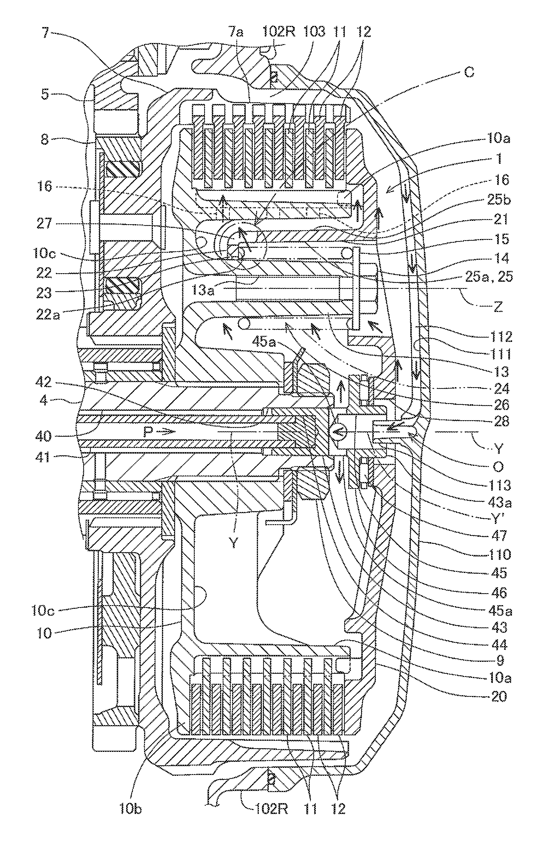
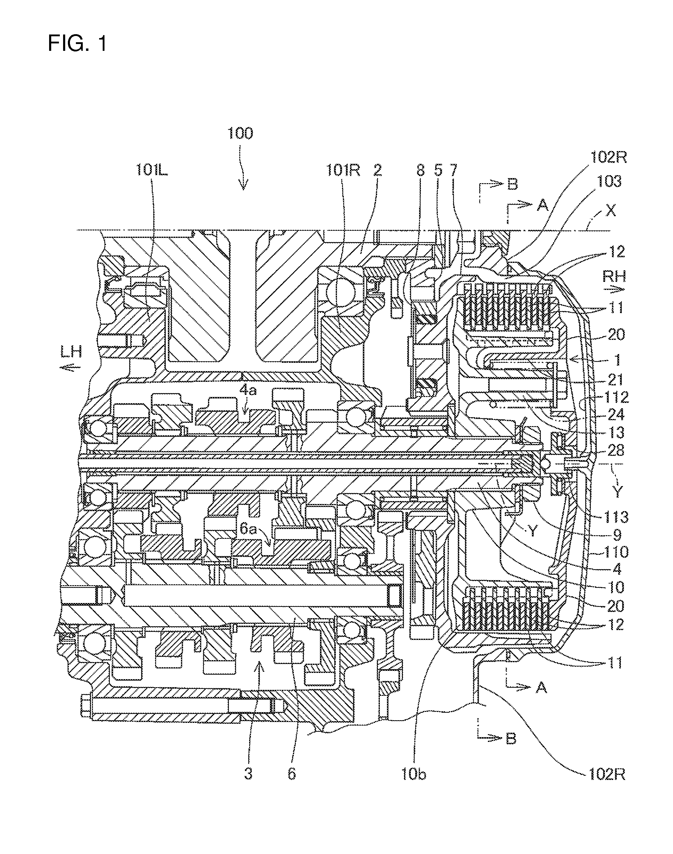
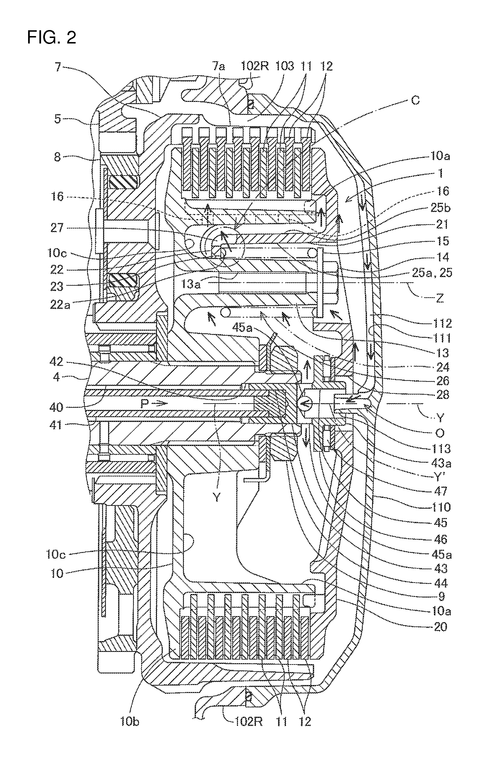
A clutch apparatus 1 according to an illustrative embodiment of the present invention will now be described with reference to FIGS. 1 to 5.

The clutch apparatus 1 according to the illustrative embodiment is a wet type multi-plate clutch apparatus provided in a power unit 100 having an internal combustion engine mounted on a vehicle such as a motorcycle and a buggy. However, the vehicle and the power unit to which the present invention is applicable are not limited. For example, the present invention is applicable also to a stationary power...


PUM


Abstract

A clutch apparatus includes a clutch outer member for supporting friction discs, which are nonrotatable relative to the clutch outer member, and are axially slidable along a clutch axis; a clutch inner member for supporting clutch discs, which are nonrotatable relative to the clutch inner member, and are axially slidable along the clutch axis, and a pressure plate having a deep recess for accommodating a clutch spring engaged with the clutch inner member. The deep recess includes a bottom portion having a spring seat for receiving the clutch spring, and a partially cylindrical shape wall portion having an axis parallel to the clutch axis. The wall portion is oriented towards the clutch axis. The deep recess has a communicating portion formed therein for establishing the communication between the inner and outer surfaces of the wall portion so as to discharge oil towards the friction and clutch discs during operation of the clutch apparatus.

Description

CROSS-REFERENCE TO RELATED APPLICATIONSThe present invention claims priority under 35 USC 119 based on Japanese patent application No. 2010-026110, filed on Feb. 9, 2010. The entire subject matter of this priority document, including specification claims and drawings thereof, is incorporated by reference herein.BACKGROUND OF THE INVENTION1. Field of the InventionThe present invention relates to a clutch apparatus for a power unit having an internal combustion engine, and to a power unit including the clutch apparatus. More particularly, the present invention relates to a clutch apparatus having a clutch outer member, a clutch inner member, and a pressure plate with a communicating portion formed therein to discharge oil from a recessed portion of the pressure plate towards friction and clutch discs supported by the clutch outer member and clutch inner member, respectively.2. Description of the Background ArtIn a wet type multi-plate clutch apparatus for a power unit having an intern...

Claims


Application Information

Patent Timeline
Patent Type & Authority Applications(United States)
IPC IPC(8): F16D13/72F16D13/52F16D13/74
CPCF16D13/52F16D13/74F16D13/72F16D13/71F16D2300/24
Inventor YAZAKI, MASAYAKOBAYASHI, ATSUSHISENDA, AKIOANZAI, SEIJI
Owner HONDA MOTOR CO LTD
Why Eureka
Try Eureka