
Reference signal for a coordinated multi-point network implementation

Active Publication Date: 2011-08-18
OT PATENT ESCROW LLC
View PDF19 Cites 421 Cited by
  • Summary
  • Abstract
  • Description
  • Claims
  • Application Information

AI Technical Summary

Problems solved by technology

As the cost of implementing such a system can be prohibitive, research is being conducted on alternative techniques to provide wide area, high data rate service.
There are several difficulties associated wit

Method used


Image

  • Reference signal for a coordinated multi-point network implementation
  • Reference signal for a coordinated multi-point network implementation
  • Reference signal for a coordinated multi-point network implementation

Examples


Embodiment Construction

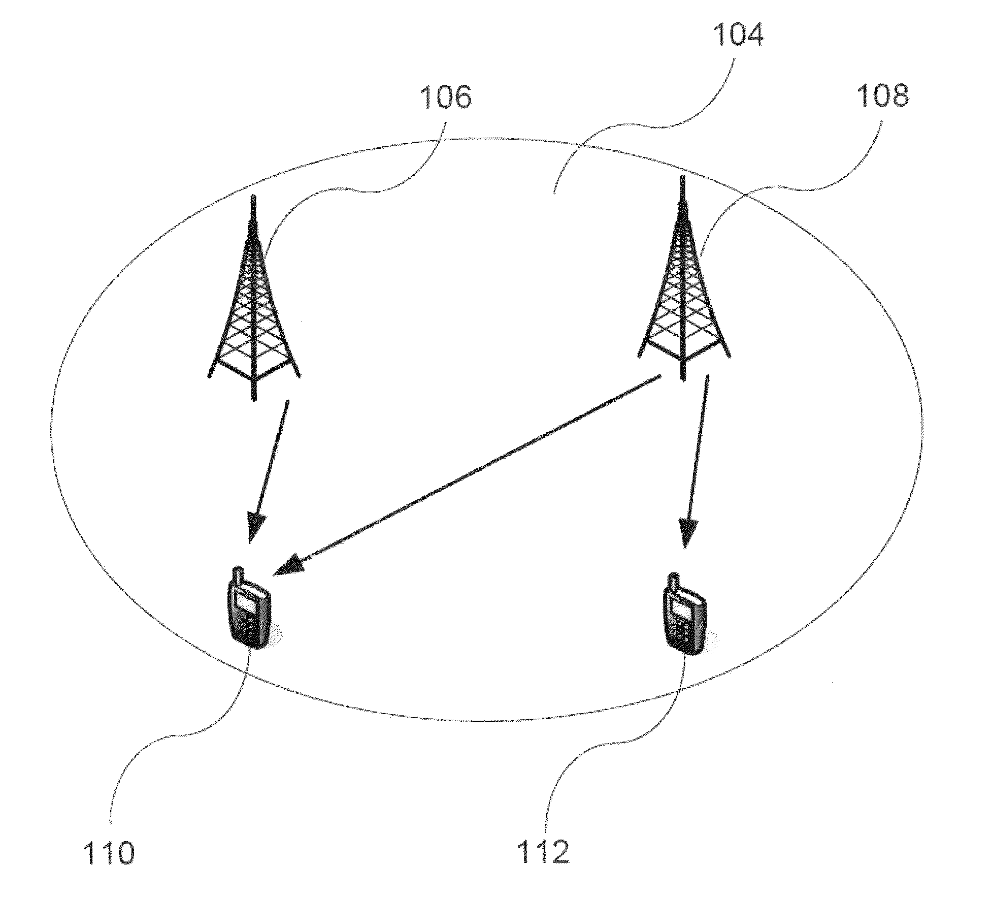
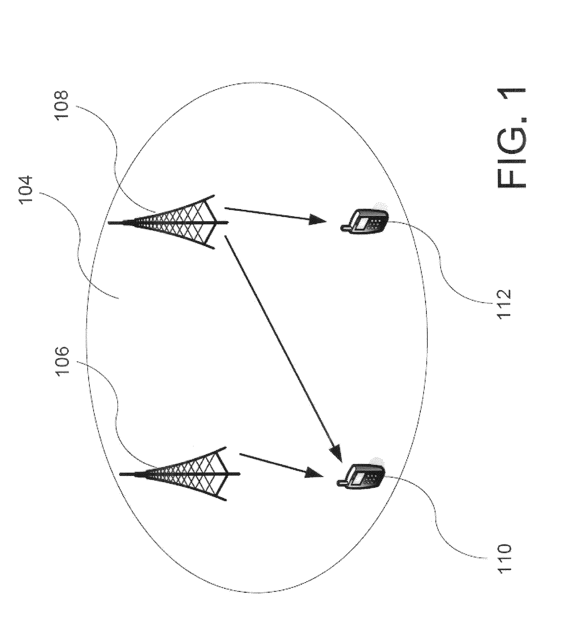
[0045]The present invention relates generally to data transmission in mobile communication systems and more specifically to a channel state information (CSI) reference signal (RS) to support coordinated multi-point (CoMP) network implementations and heterogeneous networks.

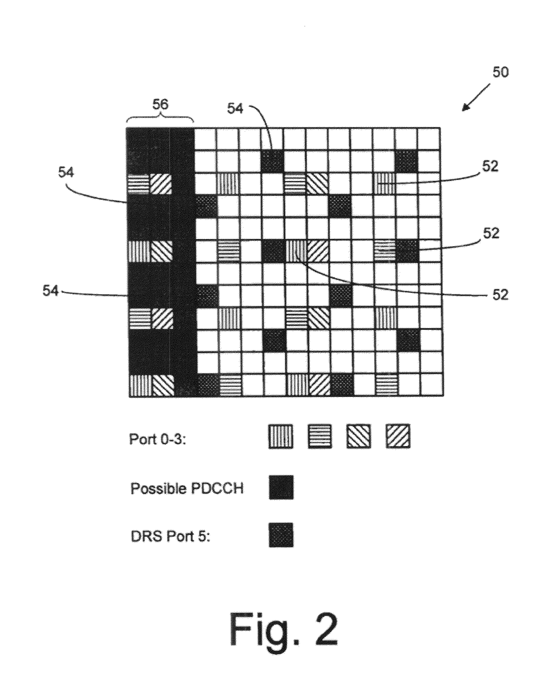
[0046]Some implementations include a method of decoding a channel state information reference signal (CSI-RS) using a user equipment (UE). The method includes receiving an indication of a resource element (RE) configuration allocated for transmission of CSI-RSs by a first cell. The indication is received from a second cell. The method includes at least one of using the indication of the RE configuration to decode a first CSI-RS received from the first cell, and using the indication of the RE configuration to mute one or more REs within a data channel transmission received from a third cell. The first cell, second cell and third cell may be associated within a CSI-RS group. At least two of the first cell, the second...


PUM


Abstract

A method of decoding a channel state information reference signal (CSI-RS) is presented. An indication of a resource element (RE) configuration allocated for transmission of CSI-RSs by a first cell is received from a second cell. The method includes at least one of using the indication of the RE configuration to decode a first CSI-RS received from the first cell, and using the indication of the RE configuration to mute one or more REs within a data channel transmission received from a third cell. The first cell, second cell and third cell may be associated within a CSI-RS group. In some cases, at least two of the first cell, the second cell, and the third cell are mutually interfering cells. The indication of the RE configuration may include a plurality of logical indices having incremental values, the plurality of logical indices identifying REs used to transmit CSI-RS.

Description

BACKGROUND[0001]The present invention relates generally to data transmission in mobile communication systems and more specifically to a channel state information (CSI) reference signal (RS) to support coordinated multi-point network implementations and heterogeneous networks.[0002]As used herein, the terms “user equipment” and “UE” can refer to wireless devices such as mobile telephones, personal digital assistants (PDAs), handheld or laptop computers, and similar devices or other User Agents (“UAs”) that have telecommunications capabilities. A UE may refer to a mobile, or wireless device. The term “UE” may also refer to devices that have similar capabilities but that are not generally transportable, such as desktop computers, set-top boxes, or network nodes.[0003]In traditional wireless telecommunications systems, transmission equipment in a base station transmits signals throughout a geographical region known as a cell. As technology has evolved, more advanced equipment has been i...

Claims


Application Information

Patent Timeline
IPC IPC(8): H04W72/04H04B1/38
CPCH04L5/0035H04L5/0091H04L5/0048H04L5/0026H04L5/0073H04L27/26
Inventor FONG, MO-HANYU, DONGSHENGXU, HUANOVAK, ROBERTGUO, SHIGUANGCAI, ZHIJUNHEO, YOUN HYOUNG
Owner OT PATENT ESCROW LLC
Learn More