Closed loop feedback system for improved down link performance

Active Publication Date: 2005-07-21
INTELLECTUAL VENTURES I LLC
View PDF47 Cites 139 Cited by
  • Summary
  • Abstract
  • Description
  • Claims
  • Application Information

AI Technical Summary

Benefits of technology

[0010] It is an object to the present invention to improve the down link performance of a cel

Problems solved by technology

In multi-path environments severe fading results when different propagation paths sum destructively at the receiving antenna.
However, the prior art does not exploit advantages provided by independent power and phase management of individual beams transmitted by different diversity type antennas to achi

Method used


Image

  • Closed loop feedback system for improved down link performance
  • Closed loop feedback system for improved down link performance
  • Closed loop feedback system for improved down link performance

Examples


Embodiment Construction

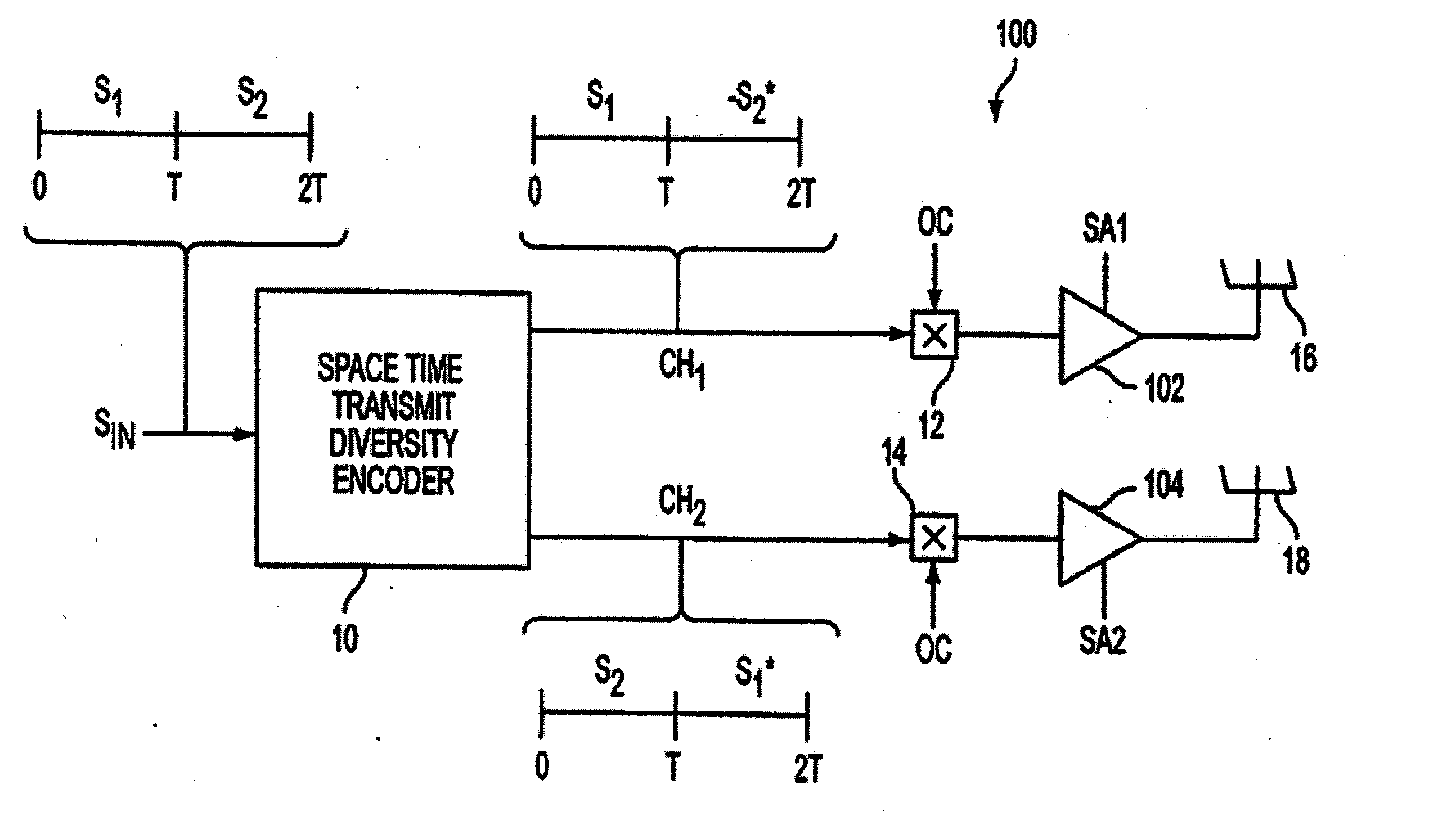
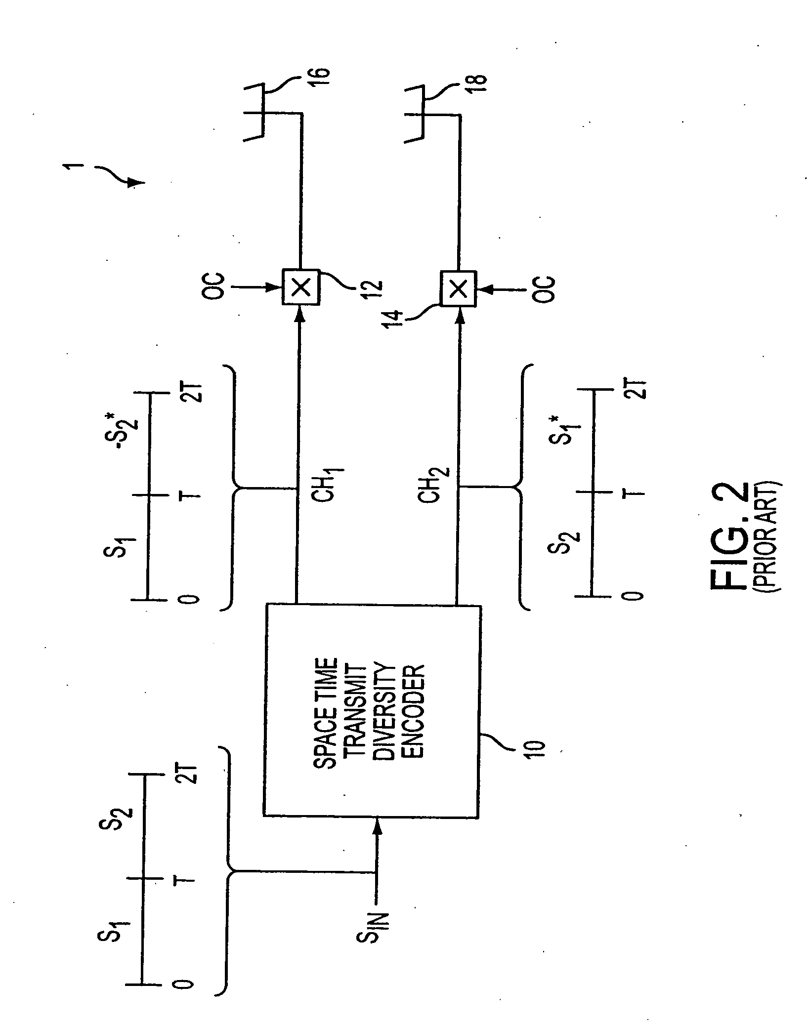
[0043] To achieve greater spectral efficiency of transmissions from the base station while minimizing co-channel interference, independent power management of individual beams transmitted by different antennas of the diversity antennas has been developed, and beamspace time encoder techniques have been developed to exploit angle of arrival diversity and exploit spatial power management of independently directed beams. Beamspace time techniques differ from known space time encoder techniques by its use of two or more independently directed orthogonal beams to exploit power and beam width management and angle of arrival diversity. Orthogonal beams are separately identifiable to the receiver by using perpendicular polarization (two beam case), by using a different pilot code for each beam in a CDMA system in addition to the CDMA spread spectrum code that is common to all beams, by using a different spread spectrum code for each beam in a CDMA system without pilot codes, by using a diff...


PUM


Abstract

A method includes receiving at least two space-time coded signals from an antenna system associated with a first station, determining complex channel state information based on the received space-time coded signals, and sending the complex channel state information to the first station. In an alternative embodiment, a method includes transmitting at least two space-time coded signals in respective beams of a multi-beam antenna array, measuring a channel impulse response for each space-time coded signal at a second station, and sending an indicia of a selected set of least attenuated signals from the second station to the first station. The multi-beam antenna array is associated with a first station. The beams transmit a signature code embedded in each respective space-time coded signal, and the signature codes are orthogonal so that the second station can separate and measure the channel impulse response corresponding to each space-time coded signal.

Description


Claims


Application Information

Patent Timeline
IPC IPC(8): H04B7/005H04B7/04H04B7/06H04B7/10H04B7/26H04J99/00H04L1/02H04L1/06H04W52/42
CPCH04B7/0408H04B7/0617H04B7/0634H04W52/42H04B7/0669H04L1/0618H04B7/0652H04B7/06H04W52/08H04W48/12H04W16/28
Inventor YLITALO, JUHAKATZ, MARCOS
Owner INTELLECTUAL VENTURES I LLC
Why Eureka
Try Eureka