
Image processing apparatus and image processing method

Active Publication Date: 2011-08-18
CANON KK
View PDF6 Cites 4 Cited by
  • Summary
  • Abstract
  • Description
  • Claims
  • Application Information

AI Technical Summary

Benefits of technology

[0014]The present invention was made in order to address the problems described above, and provides an image processing apparatus having the following function and an image processing method. That is, when performing local image processing for each of band areas obtained by dividing image data, deterioration of image quality at a band border is suppressed, while realizing a smaller-scale circuit configuration.

Problems solved by technology

In the case of using both band processing and the above-described conventional local image processing such as spatial filtering, there also exist many types of local image processing that are not applicable merely by causing band areas to overlap.
Thus, a feature of error diffusion is propagating the quantization error to the neighbor pixels, but when using both the above-described band processing and error diffusion, the quantization error is not correctly propagated at the band border, and so discontinuous deteriorated image quality unintentionally occurs in the digital halftoning data after error diffusion.
This “sweep out” is likely to occur at a band border, so that a problem also occurs in which a gap where a dot is not formed is visible as a discontinuous line or the like.

Method used


Image

  • Image processing apparatus and image processing method
  • Image processing apparatus and image processing method
  • Image processing apparatus and image processing method

Examples


first embodiment

Apparatus Configuration

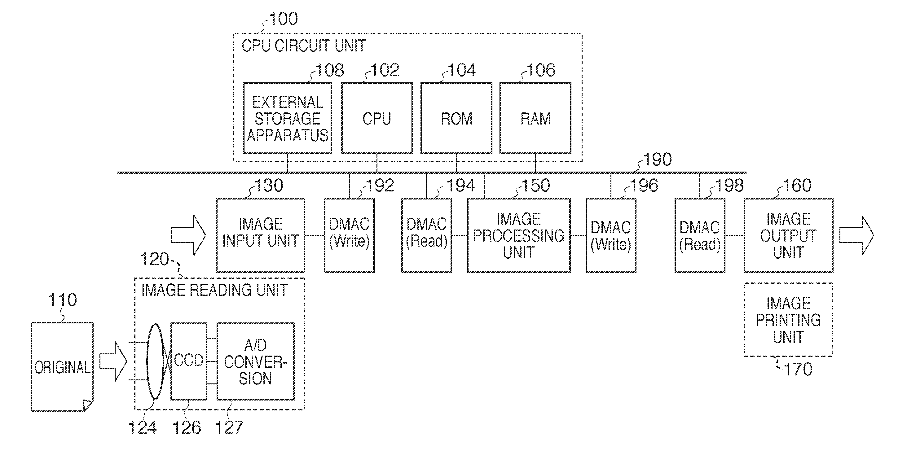
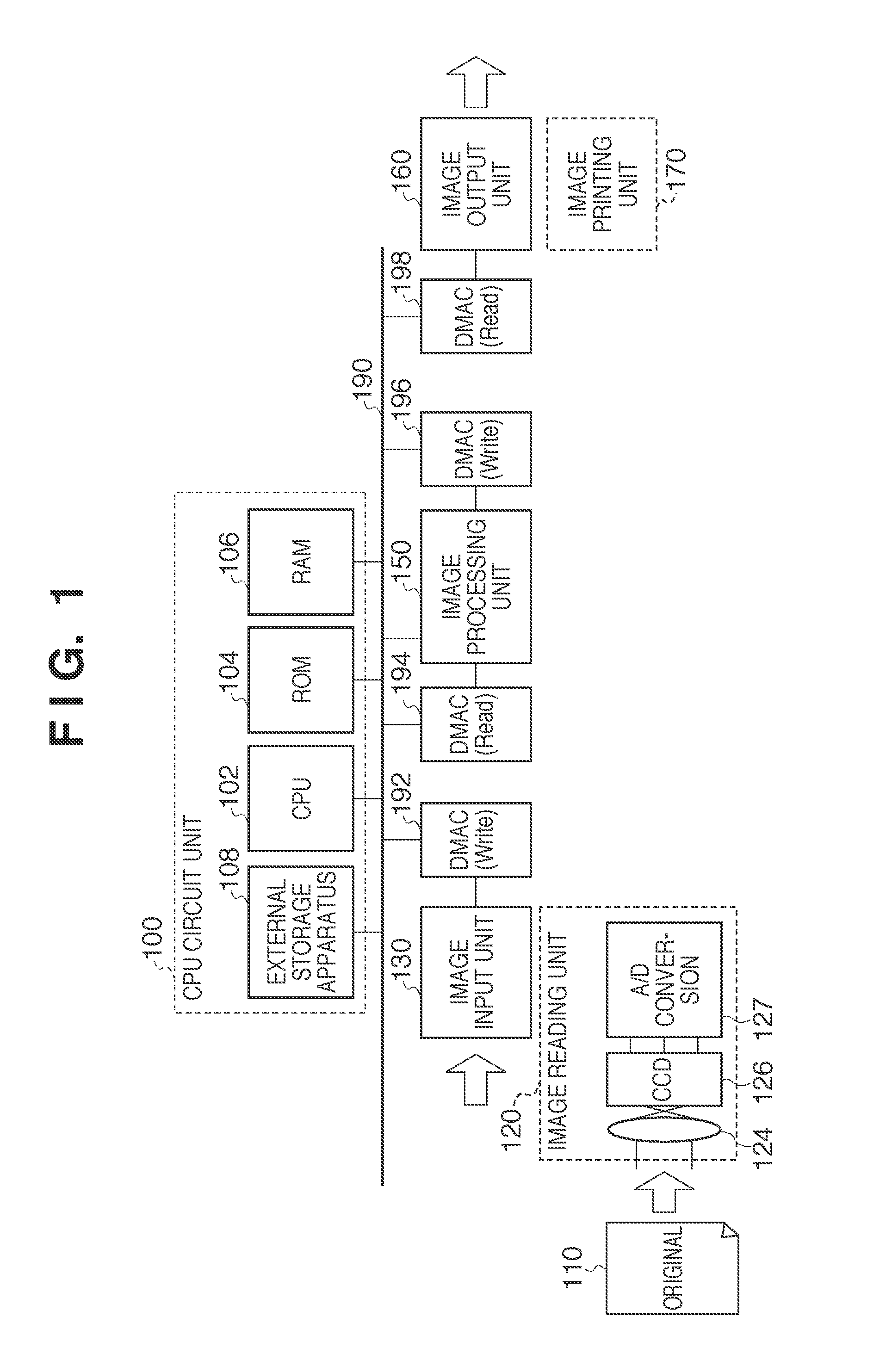
[0031]FIG. 1 is a block diagram that shows an example of the overall configuration of an image processing apparatus in the present embodiment. In FIG. 1, a CPU circuit unit 100 includes a CPU 102 for calculation and control, a ROM 104 that stores fixed data and programs, a RAM 106 used for temporarily saving data and loading programs, an external storage apparatus 108, and so forth. The CPU circuit unit 100 controls an image input unit 130, an image processing unit 150, an image output unit 160, and so forth, and performs central control of sequences of the image processing apparatus of the present embodiment. The external storage apparatus 108 is a storage medium such as a disk that stores parameters, programs, correction data, and so forth used by the image processing apparatus of the present embodiment. Data, programs, and so forth of the RAM 106 may be loaded from the external storage apparatus 108.

[0032]Any configuration where image data can be input is a...

second embodiment

[0075]Following is a description of a second embodiment according to the present invention. The configuration of the image processing apparatus in the second embodiment is the same as in the first embodiment, so a description thereof is omitted here.

[0076]In the above first embodiment, an example is described in which when using both error diffusion and band processing, deterioration of image quality due to using both error diffusion and band processing is reduced by causing the processing range to differ for each color (plane) in the band area. However, deterioration of image quality occurs not only when using both error diffusion and band processing, but also when using band processing along with correction of an image that has been read with a sensor device such as a scanner. The cause of this is that ordinarily in a sensor device, the positional relationship of sensors corresponding to each color (R, G, and B) is fixed, so offset unintentionally occurs in the read digital image ...


PUM


Abstract

An image processing apparatus for performing image processing for a plurality of band areas obtained by dividing image data is provided. The apparatus includes a dividing unit configured to divide the image data such that each of the plurality of band areas has an area overlapping an adjacent band area, and an image processing unit configured to perform the image processing for the band areas with respect to each of a plurality of planes that constitute the image data. A processing range within a band area used in the image processing by the image processing unit differs between at least two planes among the plurality of planes.

Description

BACKGROUND OF THE INVENTION[0001]1. Field of the Invention[0002]The present invention relates to an image processing apparatus and an image processing method for dividing image data into a plurality of band areas and performing local image processing for each band area.[0003]2. Description of the Related Art[0004]Ordinarily local (neighborhood) image processing such as spatial filtering is performed on the image data, when performing image forming based on digital image data. This local image processing is image processing in which some calculation is performed using all pixels included in a spatial filtering area that includes a pixel to be processed (referred to below as a pixel of interest).[0005]As shown in FIG. 3, the local image processing, for example, is performed as successive processing in band units. Here, an example is described in which spatial filtering such as edge enhancement processing or blur processing is performed on the image data. Technology is known in which, ...

Claims


Application Information

Patent Timeline
IPC IPC(8): G06K9/34
CPCH04N1/46
Inventor ITO, TADAYUKI
Owner CANON KK
Learn More