Anchoring framing to support structures

a technology of supporting structures and anchoring bolts, applied in the direction of constructions, fastening means, dowels, etc., can solve the problems of limited thickness, unnecessary duplicated labor, and insufficient extension of anchor bolts to permit nuts, so as to facilitate and expedite the fixing of plates

Inactive Publication Date: 2011-08-25
FITZPATRICK WILLIAM +1
View PDF9 Cites 0 Cited by
  • Summary
  • Abstract
  • Description
  • Claims
  • Application Information

AI Technical Summary

Benefits of technology

[0009]The present invention answers the above need by providing method and apparatus which facilitates and expedites fixing of plates to supporting concrete strata bearing anchor bolts.
[0015]The sleeve member of the threaded sleeve fastener may have a minimum length so as to minimize a gap or void which would otherwise exist below the threaded sleeve and above the support structure. The minimum length may be substantially equal to the thickness of the plate or substantially equal to the length of the plate and the thickness of the washer or washers used.
[0018]It is another object of the invention to eliminate gaps and compression of plates by members which serve to extend effective length of anchor bolts which are too short to enable ready engagement of threads using traditional methods or provide the alternative attachment method and devices disclosed herein.
[0019]It is an object of the invention to provide improved elements and arrangements thereof by apparatus for the purposes described which is inexpensive, dependable, and fully effective in accomplishing its intended purposes.

Problems solved by technology

However, in many cases, anchor bolts do not extend sufficiently to permit nuts to be threaded thereonto after the plate is in place.
This method entails unnecessary duplicated labor.
Also, in cases wherein the anchor bolt has a very limited exposed length, the portion of the plate 10 which will be under the washer is consequently limited in thickness and therefore subject to breaking or deteriorating over time under excessive compressive forces imposed by tightening the nut.

Method used


Image

  • Anchoring framing to support structures
  • Anchoring framing to support structures
  • Anchoring framing to support structures

Examples


Embodiment Construction

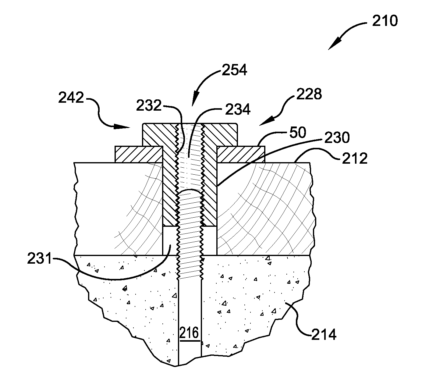
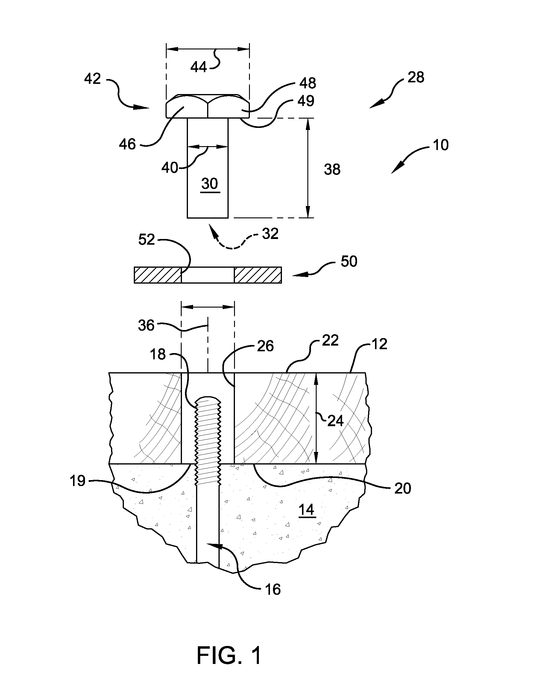
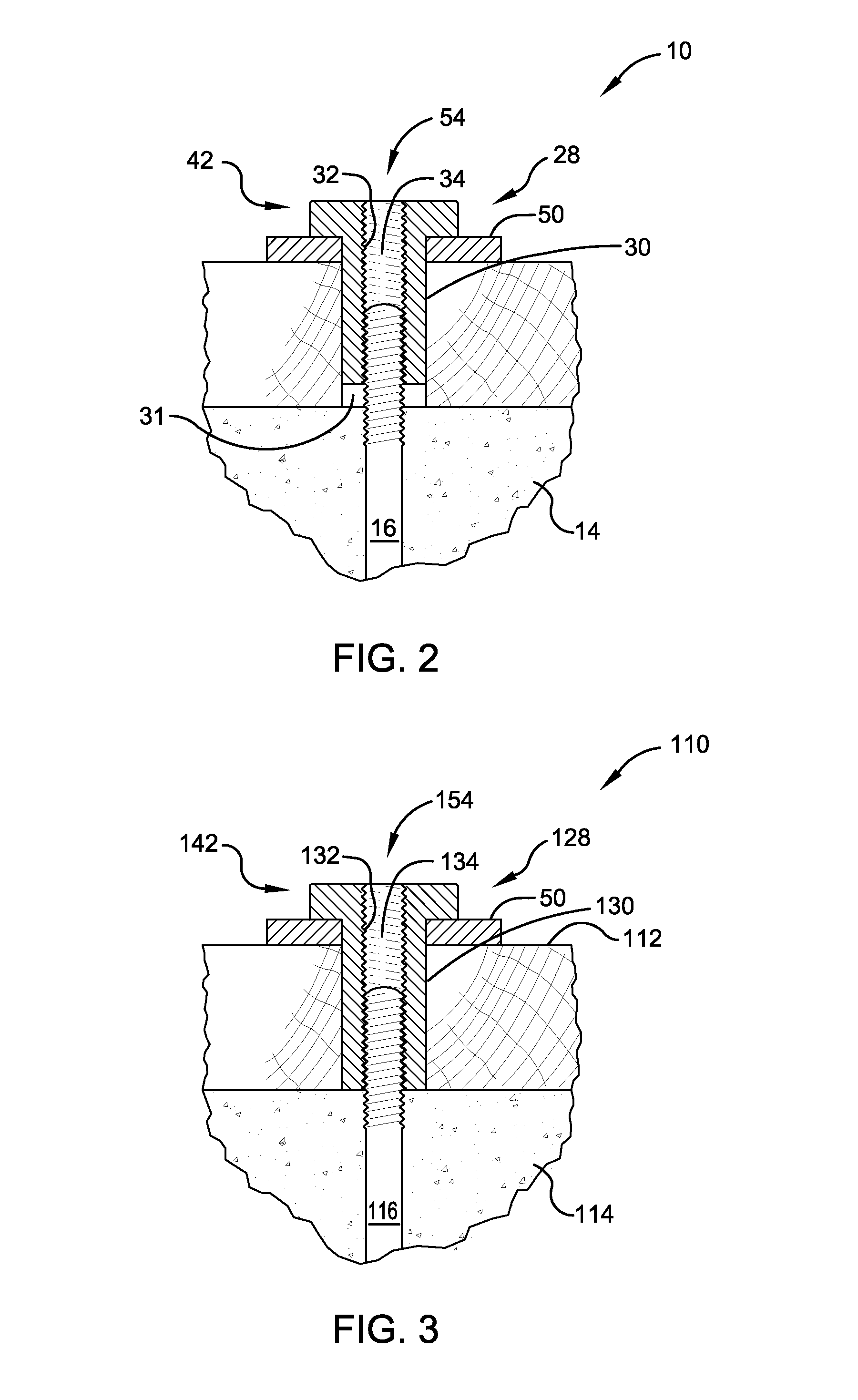
[0031]FIGS. 1 and 2 show an exemplary construction 10 according to at least one aspect of the invention. The exploded view of FIG. 1 shows a framing plate 12 which has been placed onto the upper surface of a support structure, in this example, a concrete structure 14 which serves to provide a supporting stratum for the plate 12. The concrete structure 14 may be any other type of support structure, which presents an exposed surface to which further building structure will subsequently be attached, as such, as used herein, a “support structure” includes, but is not limited to: upwardly exposed foundation walls, concrete masonry unit or block walls, vertical columns, wood or steel beams (tube or I-beams), and slabs.

[0032]An anchor bolt 16 is embedded within the concrete structure 14. The anchor bolt performs the conventional function of providing a convenient and effective way of fastening framing members generally, and more particularly, horizontally oriented plates such as the plate ...


PUM


Abstract

Fixing a framing plate to a support structure, using one or more anchor bolts embedded within the support structure. A first hole drilled into the plate is to an oversize diameter which accepts a threaded sleeve. The threaded sleeve extends an effective length of the anchor bolt and may comprise a drive head and an interference member, which engages the plate directly or through a washer to fix the plate to the support structure.

Description

CROSS-REFERENCE TO RELATED APPLICATION[0001]This divisional patent application claims priority to U.S. Non-Provisional patent application Ser. No. 12 / 123,843 filed May 20, 2008; the contents of which are incorporated herein.FIELD OF THE INVENTION[0002]The present invention relates to method and apparatus for anchoring framing elements of building structures to support structures such as a concrete foundation.BACKGROUND OF THE INVENTION[0003]Many buildings structures, such as houses, are built using framing, such as wood framing, secured to a foundation, such as a poured concrete foundation. Subsequent building may include building a wooden frame on the foundation. Attachment of wooden framing is typically accomplished by fixing horizontal framing members, usually called plates or ledgers, to the upper exposed surfaces of the foundation.[0004]Attachment of plates may rely upon anchor bolts, which are embedded within the concrete when the latter is poured. Anchor bolts leave a certain...

Claims


Application Information

Patent Timeline
Patent Type & Authority Applications(United States)
IPC IPC(8): F16B13/04
CPCF16B37/145E02D27/00
Inventor FITZPATRICK, WILLIAMSCOTT, CRAIG
Owner FITZPATRICK WILLIAM
Why Eureka
Try Eureka