Versatile fastener

Active Publication Date: 2011-09-22
ESSENCE METHOD REFINE
View PDF6 Cites 6 Cited by
  • Summary
  • Abstract
  • Description
  • Claims
  • Application Information

AI Technical Summary

Benefits of technology

[0008]The object of the present invention is to provide a versatile fastener for avoiding an unstable drilling as well as a cracked obje

Problems solved by technology

As a result, the debris generated in time of screwing is readily retained in the guiding area 141, hence incurring a poor guiding effect.
Therefore, if a rotating force is continuously executed on the screw 1, the debris will be adversely compressed in view of the unfavorable guiding effect; additio

Method used


Image

  • Versatile fastener
  • Versatile fastener
  • Versatile fastener

Examples


Embodiment Construction

[0025]Before describing in greater detail, it should note that the like elements are denoted by the similar reference numerals throughout the disclosure.

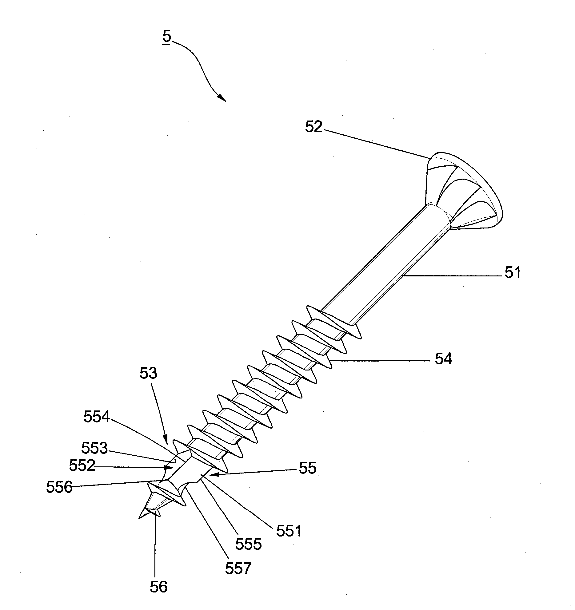
[0026]FIG. 3 shows a first preferred embodiment of the present invention. A versatile fastener 5 comprises a shank 51, a head portion 52 and a drill point 53 respectively disposed at two opposite ends of the shank 51, and a threaded section 54 spirally disposed on the shank 51. Wherein, a cutting part 55 with no threaded portion disposed thereon is formed on the drill point 53, and at least one leading thread 56 outwardly extending from the cutting part 55. Herein, by means of forming the cutting part 55 through the directly punching, a higher strength of the cutting part 55 could be accomplished.

[0027]Further, the cutting part 55 includes at least two flat areas 551 and an accommodating area 552 defined between any two of the flat areas 551 at intervals. As it should be, the cutting part 55 could alternatively include several flat ...


PUM

PropertyMeasurementUnit
Lengthaaaaaaaaaa
Electrical resistanceaaaaaaaaaa
Areaaaaaaaaaaa

Abstract

The present invention pertains to a versatile fastener essentially comprising at least two flat areas formed on a cutting part, and an accommodating area disposed between any two of the flat areas. Wherein, at least two cutting faces are convergent to form the accommodating area, a first and a second cutting edges are respectively formed at a connection between each cutting face and flat area. In operation, the flat areas facilitate the first and the second cutting edges to promote a stable balance with the object, thereby allowing the debris to be swiftly guided out of the accommodating areas. Consequently, it is difficult to crack the object while imparting forces thereon so as to lower the screwing resistance and the fastening torque as well as preferably increase the combining efficiency.

Description

BACKGROUND OF THE INVENTION[0001]1. Field of the Invention[0002]The present invention relates to a fastener, in particular to a versatile fastener that provides a preferable stability in time of fastening and favorably decreases the screwing torque as well as the resistance.[0003]2. Description of the Related Art[0004]A conventional screw 1 shown in FIG. 1 generally comprises a shank 11, a head portion 12 disposed at one end of the shank 11, and a plurality of threads 13 spirally disposed on the shank 11. Wherein, a free end 14 is formed at the other end of the shank 11. The free end 14 includes a guiding area 141 defined on the surface thereof as well as extensively formed in the connection with the threads 13, and a cutting edge 142 defined on a congregation formed by the guiding area 141, the free end 14, and the threads 13. In applying the screw 1 for fastening, the free end 14 of the screw 1 is propped against an object 2; thence, the free end 14 leads the entire screw 1 to gra...

Claims


Application Information

Patent Timeline
IPC IPC(8): F16B25/10
CPCF16B25/0015F16B25/0052F16B25/106F16B25/0084F16B25/0078
Inventor CHANG, CHING-HSIANG
Owner ESSENCE METHOD REFINE
Why Eureka
Try Eureka