Method of manufacturing disk drive apparatus and method of manufacturing spindle motor

a technology of disk drive and manufacturing method, which is applied in the manufacture of stator/rotor bodies, instruments, record information storage, etc., can solve the problems of contaminating the disk and generating particles

Inactive Publication Date: 2014-03-27
NIPPON DENSAN CORP
View PDF0 Cites 0 Cited by
  • Summary
  • Abstract
  • Description
  • Claims
  • Application Information

AI Technical Summary

Benefits of technology

[0013]The fourth preferred embodiment of the present invention makes it possible to manufacture the spindle motor with the start position of the hub screw groove being identifiable based on the hub information mark.

Problems solved by technology

In this case, the hub and the spacer are rotated relative to each other while being in contact with each other, and this may result in generation of a particle.
The particle generated may become attached to the disk, thereby contaminating the disk.

Method used


Image

  • Method of manufacturing disk drive apparatus and method of manufacturing spindle motor
  • Method of manufacturing disk drive apparatus and method of manufacturing spindle motor
  • Method of manufacturing disk drive apparatus and method of manufacturing spindle motor

Examples


Embodiment Construction

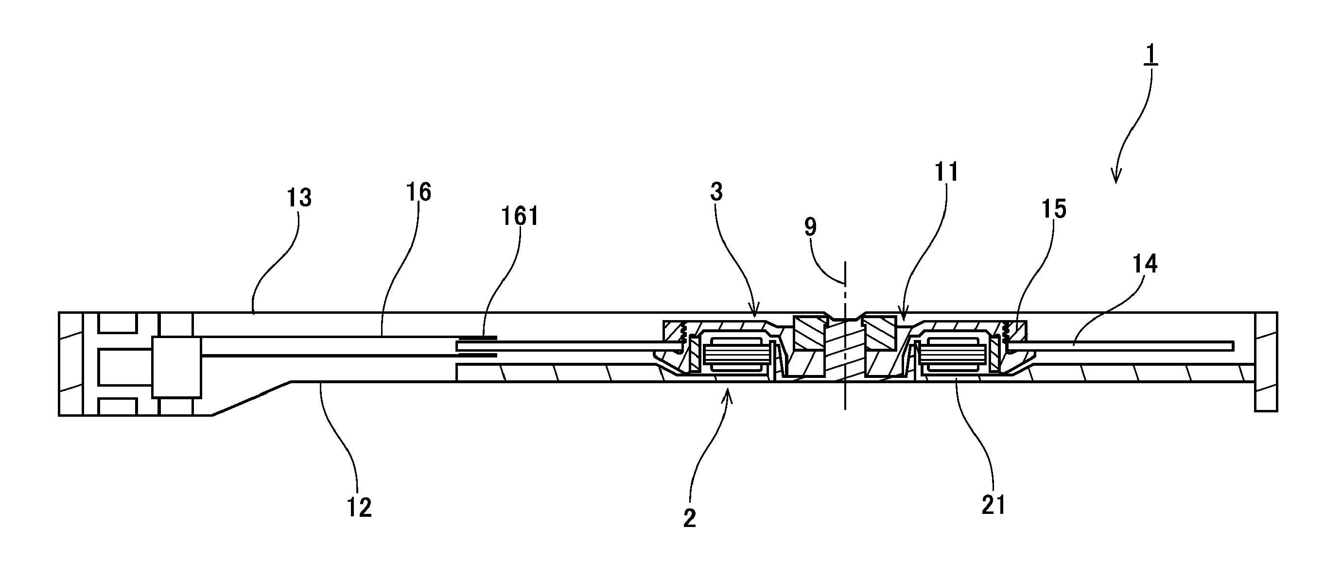
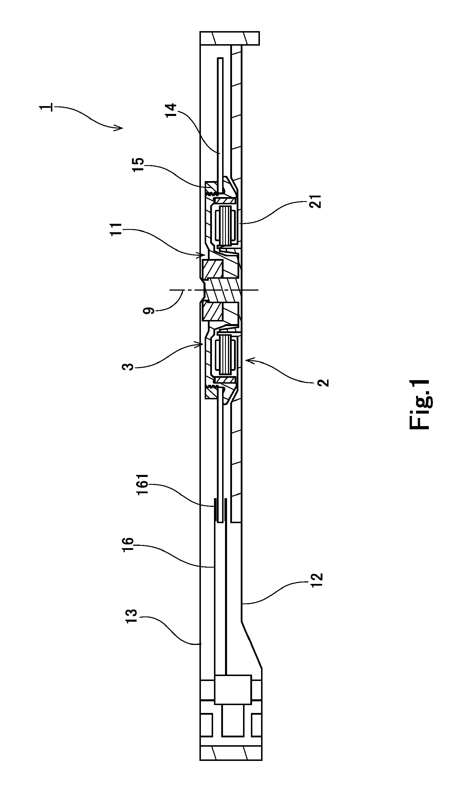
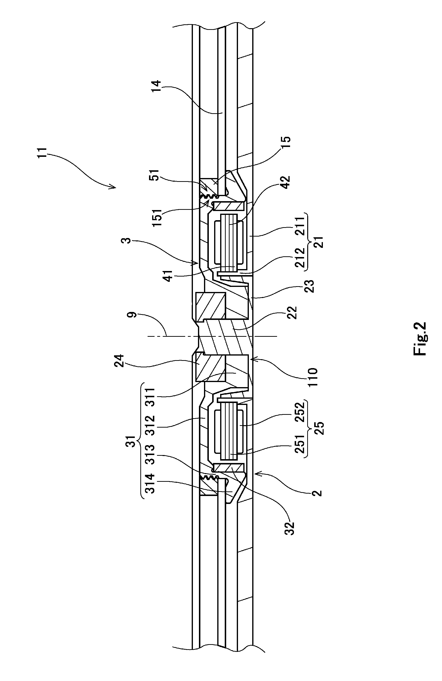
[0027]Hereinafter, preferred embodiments of the present invention will be described with reference to the accompanying drawings. It is assumed herein that a direction parallel or substantially parallel to a central axis of a spindle motor is referred to by the term “axial direction”, “axial”, or “axially”, that directions perpendicular or substantially perpendicular to the central axis of the spindle motor are each referred to by the term “radial direction”, “radial”, or “radially”, and that a direction along a circular arc centered on the central axis of the spindle motor is referred to by the term “circumferential direction”, “circumferential”, or “circumferentially”. It is also assumed herein that a vertical direction is the axial direction, and that a side on which a recording disk is arranged with respect to a base portion of the spindle motor is defined as an upper side. The shape of each member or portion and relative positions of different members or portions will be describ...


PUM

PropertyMeasurementUnit
angleaaaaaaaaaa
image processingaaaaaaaaaa
shapeaaaaaaaaaa

Abstract

A disk drive apparatus includes a rotor hub including an outer surface with a hub screw groove and a hub information mark indicative of a start position of the hub screw groove. A method of manufacturing the disk drive apparatus includes the steps of preparing a spindle motor including the rotor hub, preparing a clamper including a clamper screw groove, and fitting a recording disk to the spindle motor. The method further includes the steps of detecting a position of the hub information mark and, based on the detected position of the hub information mark, positioning each of the clamper and the spindle motor in a circumferential direction, and screwing the clamper to the spindle motor.

Description

BACKGROUND OF THE INVENTION[0001]1. Field of the Invention[0002]The present invention relates to a method of manufacturing a disk drive apparatus, and a method of manufacturing a spindle motor.[0003]2. Description of the Related Art[0004]A spindle motor arranged to rotate a disk is installed in a disk drive apparatus. A known spindle motor and a known disk drive apparatus are described, for example, in JP-A 2001-35129. In the disk drive apparatus described in JP-A 2001-35129, a disk is adhered to a spacer including an inner circumferential portion with a screw groove defined therein, and this spacer is screwed to an outer circumferential portion of a hub, the outer circumferential portion including a screw groove defined therein, whereby the disk is fixed to the hub (see, for example, paragraph [0014] of JP-A 2001-35129).[0005]In the case of the disk drive apparatus described in JP-A 2001-35129, when the spacer is screwed to the hub, the hub and the spacer are rotated relative to ea...

Claims


Application Information

Patent Timeline
Patent Type & Authority Applications(United States)
IPC IPC(8): H02K15/02G11B19/20
CPCG11B19/2009H02K15/02Y10T29/49012
Inventor SHIRAISHI, MASAHIROSATOMORITA, TSUYOSHI
Owner NIPPON DENSAN CORP
Why Eureka
Try Eureka