Arcuate fixation member

Active Publication Date: 2011-09-22
DEPUY SYNTHES PROD INC
View PDF64 Cites 268 Cited by
  • Summary
  • Abstract
  • Description
  • Claims
  • Application Information

AI Technical Summary

Benefits of technology

[0004]In accordance with one embodiment, a bone fixation member configured to be inserted in a vertebral body includes a fixation body having opposing proximal and distal ends and a curved intermediate portion extending between the proximal and distal ends. A tip configured

Problems solved by technology

However, in a variety of surgical situations, achieving a desired trajectory for screw ins

Method used


Image

  • Arcuate fixation member
  • Arcuate fixation member
  • Arcuate fixation member

Examples


Embodiment Construction

[0055]Certain terminology is used in the following description for convenience only and is not limiting. The words “right”, “left”, “top” and “bottom” designate directions in the drawings to which reference is made. The words “inwardly” and “outwardly” refer to directions toward and away from, respectively, the geometric center of the device and designated parts thereof. The words, “anterior”, “posterior”, “superior”, “inferior”, “lateral”, “medial”, “sagittal”, “axial”, “coronal,”“cranial,”“caudal” and related words and / or phrases designate preferred positions and orientations in the human body to which reference is made and are not meant to be limiting.

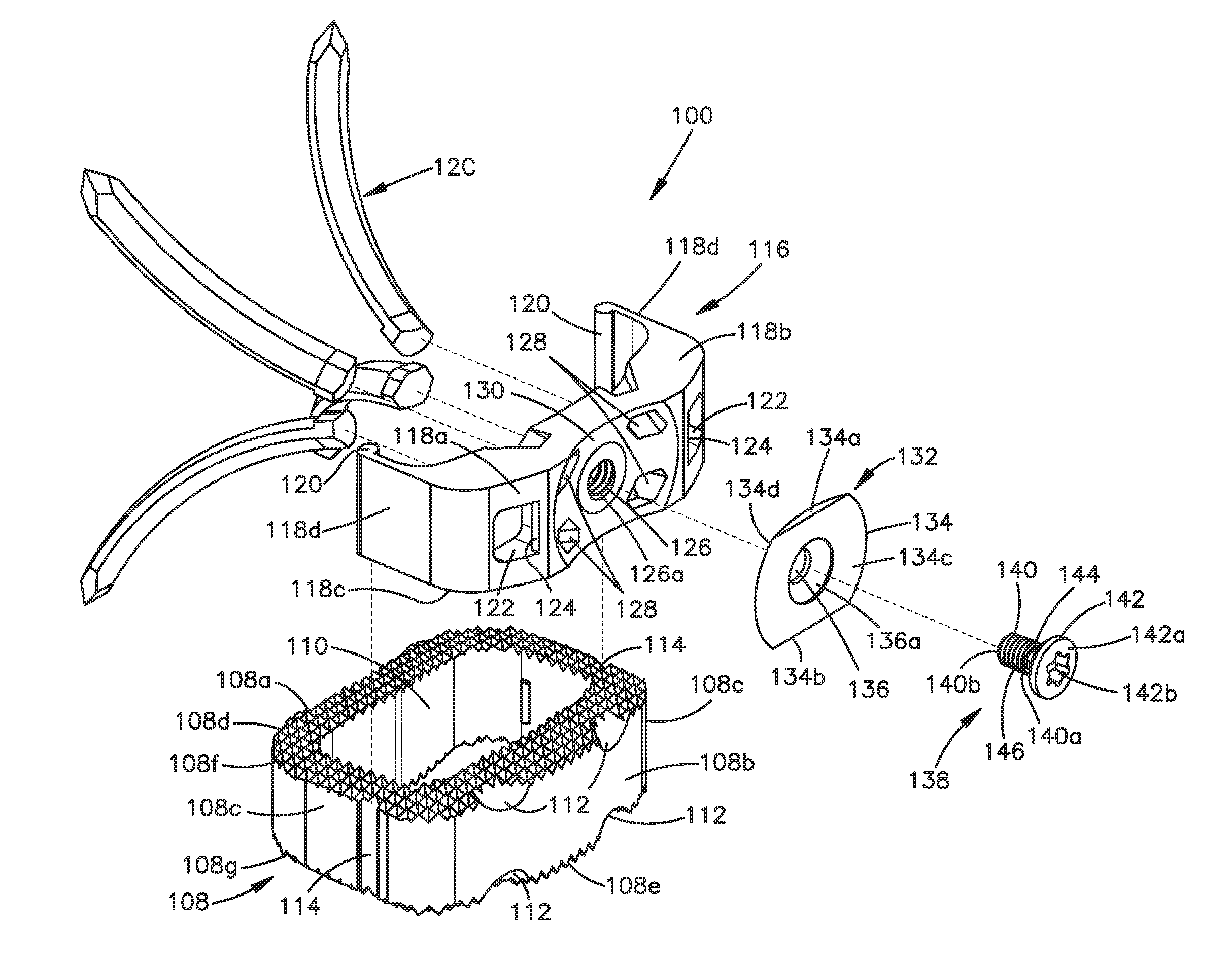
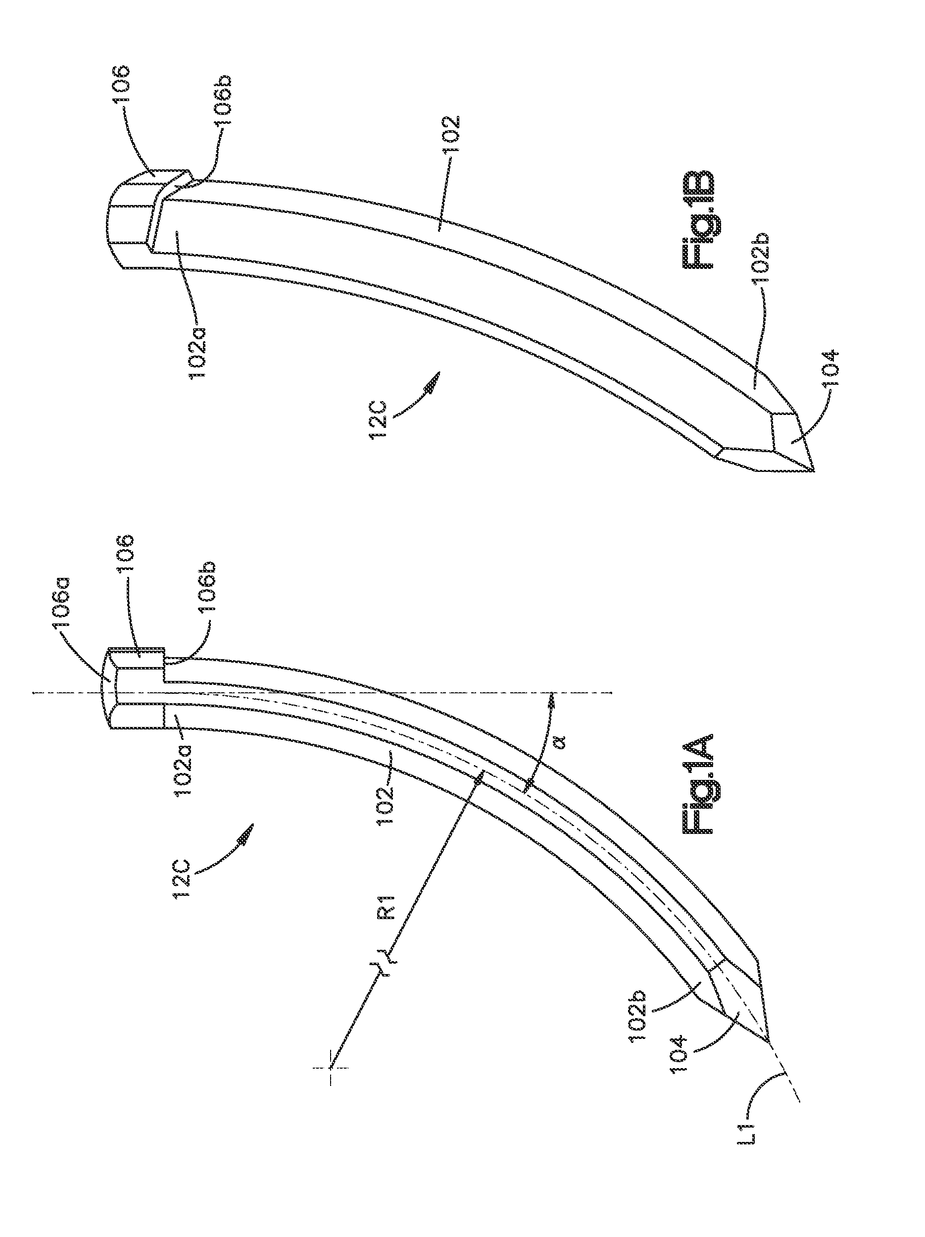
[0056]The words “arcuate” and “curved” as used herein refer generally to the varying physical geometry of an object along an axis coincident to the object, for example the deviation from straightness of the body of an arcuate fixation member along a central longitudinal axis defined within the body of the object between its proximal...


PUM


Abstract

Arcuate fixation members with varying configurations and/or features are provided, along with additional components for use therewith in provided intervertebral implants. The arcuate fixation members may be of different lengths, cross sectional geometries, and/or cross sectional areas. Applications of intervertebral implants utilizing arcuate fixation members are particularly suitable when a linear line-of-approach for delivering fixation members is undesirable.

Description

CROSS-REFERENCE TO RELATED APPLICATIONS[0001]This patent application is a continuation-in-part of and claims priority to U.S. patent application Ser. No. 12 / 761,101, filed Apr. 15, 2010. U.S. patent application Ser. No. 12 / 761,101 claims priority to U.S. provisional patent application No. 61 / 169,461, filed Apr. 15, 2009. The disclosures of U.S. patent application Ser. No. 12 / 761,101 and U.S. provisional patent application No. 61 / 169,461 are hereby incorporated by reference as if set forth in their entireties herein.TECHNICAL FIELD[0002]The present disclosure relates generally to orthopedics, and in particular relates to fixation systems, intervertebral implants, and associated surgical methods and procedures for using same.BACKGROUND[0003]Spinal fixation systems such as pedicle screw and rod constructs are commonly used to promote fusion between intervertebral bodies. The insertion of pedicle screws typically requires a linear “line-of-approach” trajectory that is aligned with the l...

Claims


Application Information

Patent Timeline
IPC IPC(8): A61F2/44A61B17/70
CPCA61B17/70A61F2310/00359A61B17/92A61B2017/8655A61F2/28A61F2/30744A61F2/30965A61F2/442A61F2/4455A61F2/4465A61F2/4611A61F2002/2835A61F2002/30387A61F2002/30509A61F2002/30514A61F2002/30517A61F2002/30578A61F2002/30604A61F2002/30616A61F2002/30777A61F2002/30784A61F2002/30787A61F2002/30841A61F2002/30843A61F2002/30845A61F2002/4475A61F2002/4627A61F2002/4628A61F2220/0025A61F2310/00017A61F2310/00023A61F2310/00131A61B17/7056A61F2220/0016A61F2002/30507A61F2002/30593A61B17/846
Inventor DONNER, THOMASSCHOENLY, JAREDEVANS, DAVIDGFELLER, ANDREAS
Owner DEPUY SYNTHES PROD INC
Why Eureka
Try Eureka