
Stack valve

a technology of stout valve and stout, which is applied in the direction of fluid coupling, positive displacement liquid engine, servomotor, etc., and can solve problems such as poor operation

Active Publication Date: 2011-09-29
NABLESCO CORP
View PDF2 Cites 8 Cited by
  • Summary
  • Abstract
  • Description
  • Claims
  • Application Information

AI Technical Summary

Benefits of technology

[0014]The stack valve of the present invention allows an actuator connected to a direction switching valve on the upstream side to be operable when an actuator connected to a direction switching valve on the downstream side is stopped for reasons such as overload, even if this direction switching valve is not returned to the neutral position by the operator.

Problems solved by technology

The stack valve of Patent Document 1 is disadvantageous in that, provided that an operator operates the service valve 13 to activate an attachment connected to the service valve 13 via an actuator and then the attachment is stopped for reasons such as physical contact with an object, the boom and the bucket do not move even if the boom direction switching valve 11 and the bucket direction switching valve 12 are operated.
The operationality is poor in this case, because the boom and the bucket do not return to be movable unless the service valve 13 is returned to the neutral position.

Method used


Image

  • Stack valve
  • Stack valve
  • Stack valve

Examples


first embodiment

[0018](Structure of Stack Valve)

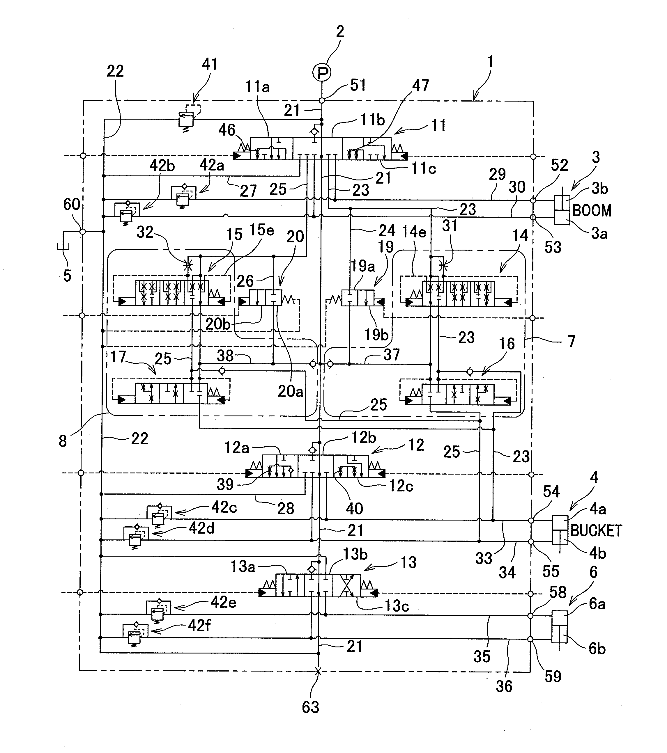
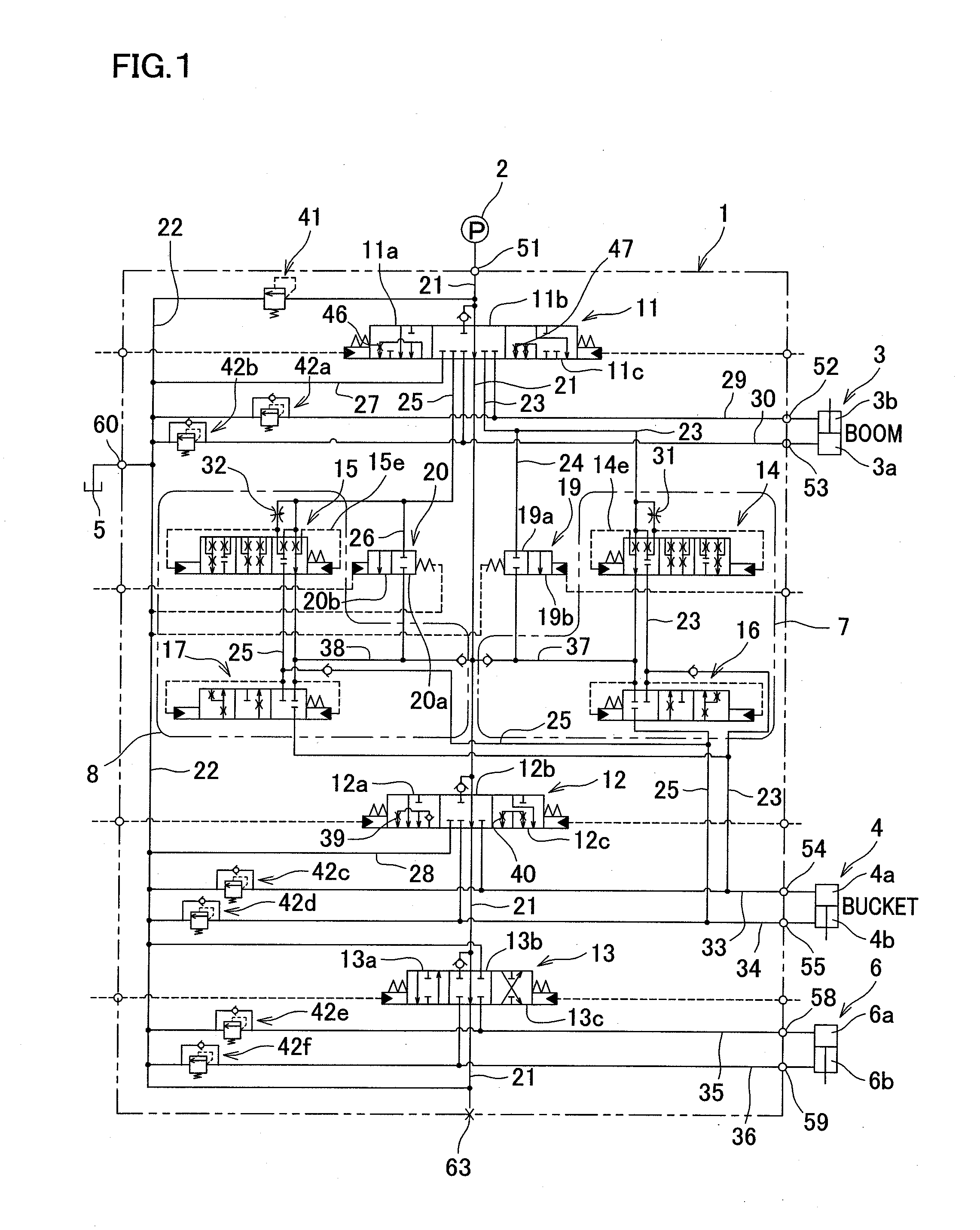
[0019]Referring to FIG. 1, a stack valve 1 according to First Embodiment of the present invention will be described. The stack valve 1 is a stack valve having a bucket parallel movement function and is chiefly used for construction machines such as loaders (not illustrated). Such a loader is provided with hydraulically operated components such as a boom (not illustrated) capable of moving up and down and attached to the front part of the loader and a bucket (not illustrated) which is attached to the leading end of the boom. The boom is moved by the boom cylinder 3. This boom is raised when a pressure fluid is supplied to a head-side chamber 3a of a boom cylinder 3 and is lowered when a pressure fluid is supplied to a rod-side chamber 3b. The bucket is moved by the bucket cylinder 4. The bucket performs dumping (forward tilting) as a pressure fluid is supplied to a head-side chamber 4a of a bucket cylinder 4, and is moved in the scooping direction (bac...

second embodiment

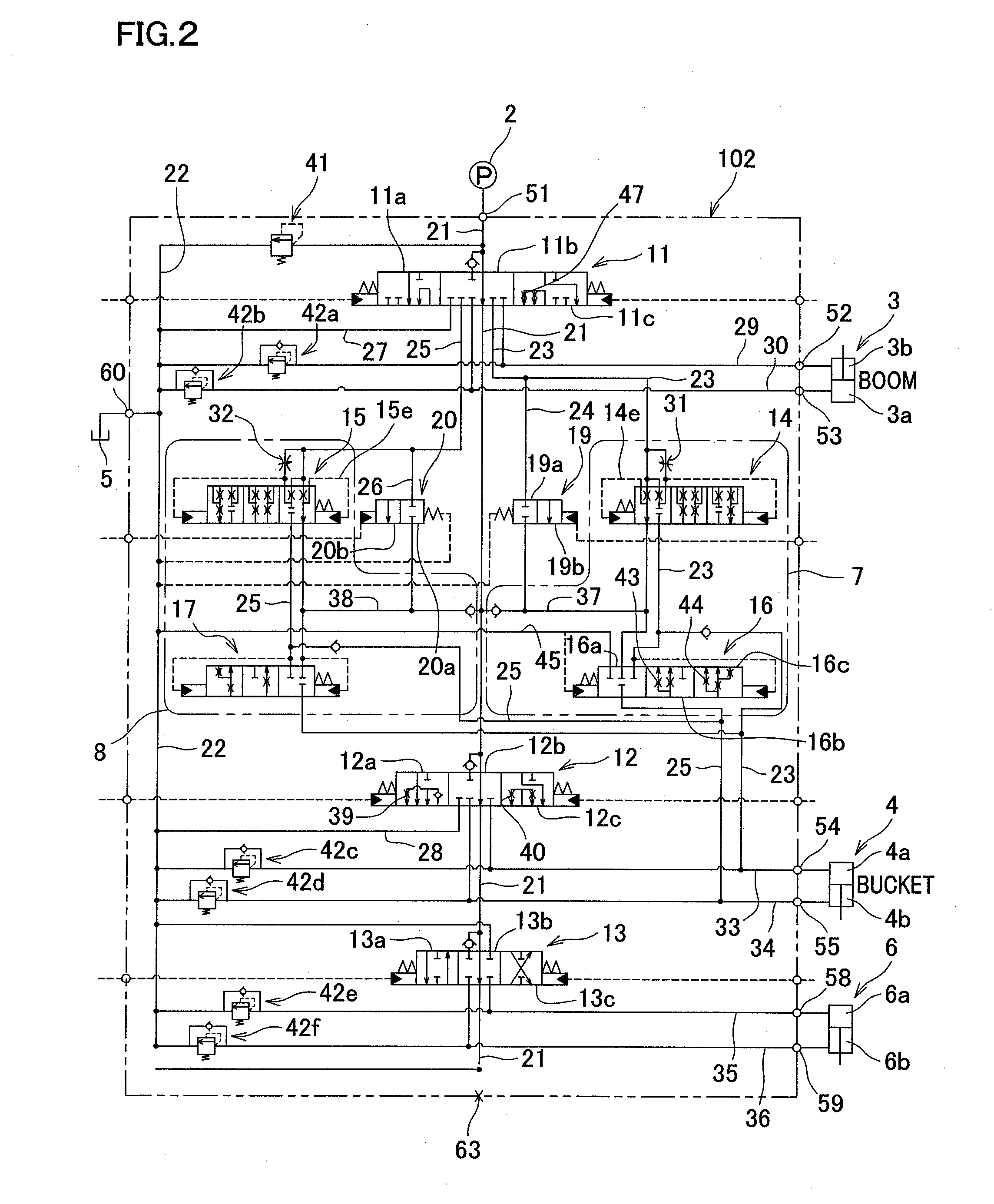
[0061]FIG. 2 is a hydraulic circuit diagram showing a stack valve 102 according to Second Embodiment of the present invention. The stack valve 1 of First Embodiment and the stack valve 102 of the present embodiment are different from each other in the structure of the ascending position 11a of the boom direction switching valve 11 and the structure of the ascending sequence valve 16.

[0062]In the present embodiment, the return pressure fluid from the supply and discharge path 29 does not flow into the tank path 22 even if the boom direction switching valve 11 is switched to the ascending position 11a.

[0063]The ascending sequence valve 16 of the present embodiment has changeover positions 16b and 16c at which the supply and discharge path 34 is connected to the ascending return path 37 (i.e. the unloading path 21 on the downstream of the boom direction switching valve 11) and the tank path 22. The ascending sequence valve 16 is connected to a sequence valve tank return path 45.

[0064]...


PUM


Abstract

A stack valve 1 includes a boom direction switching valve 11 (first direction switching valve) connected to an unloading path 21 and a service valve 13 (second direction switching valve) connected to the unloading path 21 at the downstream of the boom direction switching valve 11. At changeover positions 11a and 11c at which the unloading path 21 on the upstream side is connected to one of the supply and discharge paths 29 and 30 and the other one of the supply and discharge paths 29 and 30 is connected to the unloading path 21 on the downstream side, the boom direction switching valve 11 is connected to a boom valve tank return path 27 which connects the other one of the supply and discharge paths 29 and 30 with the tank path 22.

Description

CROSS REFERENCE TO RELATED APPLICATION[0001]The present application claims priority from Japanese Patent Application No. 2010-075359, which was filed on Mar. 29, 2010, the disclosure of which is herein incorporated by reference in its entirety.BACKGROUND OF THE INVENTION[0002]The present invention relates to a stack valve mainly used in construction machines and controlling a plurality of actuators.[0003]An example of such a technology is recited in Patent Document 1. A stack valve recited in Patent Document 1 is a stack valve having a bucket parallel movement function of keeping a bucket in parallel to the horizontal plane when a boom is driven by supplying a pressure fluid to a boom cylinder, by supplying a return pressure fluid from a bucket cylinder to the boom cylinder.Patent Documents[0004][Patent Document 1] Japanese Unexamined PatentSUMMARY OF THE INVENTION[0005]The stack valve of Patent Document 1 is disadvantageous in that, provided that an operator operates the service va...

Claims


Application Information

Patent Timeline
IPC IPC(8): F15B13/02
CPCE02F3/436E02F9/2225E02F9/2282F15B2211/421F15B2211/3111F15B2211/4053F15B2211/41509F15B11/16Y10T137/86059Y10T137/87217F15B11/22E02F9/22
Inventor MIKI, TAKASHI
Owner NABLESCO CORP
Learn More