Shock-protecting packaging

a packaging and shock-protection technology, applied in the field of packaging, can solve the problems of ridges and grooves on the edges of two of the flanges opposite one another that are not compatible, and are generally labor-intensiv

Active Publication Date: 2011-09-29
PROTECTIVE PACKAGING SYST EUROPE BV
View PDF16 Cites 18 Cited by
  • Summary
  • Abstract
  • Description
  • Claims
  • Application Information

AI Technical Summary

Benefits of technology

[0006]It is one of the objects of the present invention to provide a form of thermoformed packaging case by which the above disadvantage can be overcome.

Problems solved by technology

These methods, in addition to being generally labor-intensive, commonly involve a substantial outlay in cost and material-resources on packaging items in the form, for example, of cardboard cases and specially-designed items of plastics foam and corrugated cardboard to fit within them.
There is, however, a limitation with the known form of packaging case on the extent to which the advantage of the mutual ridge-within-groove nesting can be achieved in practice between all flanges.
In the case described, the ridges and grooves on the edges of two of the flanges opposite one another are not compatible with achieving nesting between them in that there is ridge-to-ridge alignment between them rather than the ridge-to-groove alignment required for nesting.
There is in consequence a gap between those two flanges with the disadvantage that the benefits of interlocking and direct cushioning or absorption of shock between them is not realized.

Method used


Image

  • Shock-protecting packaging
  • Shock-protecting packaging
  • Shock-protecting packaging

Examples


Embodiment Construction

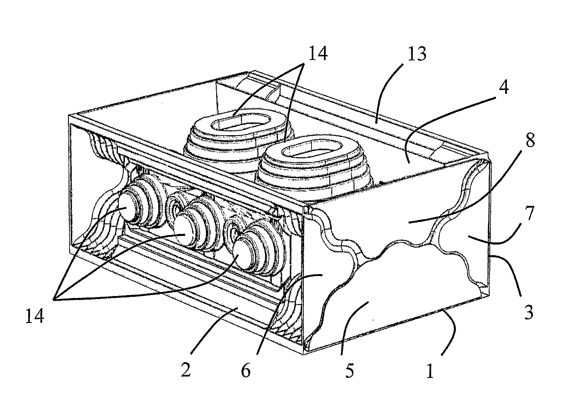
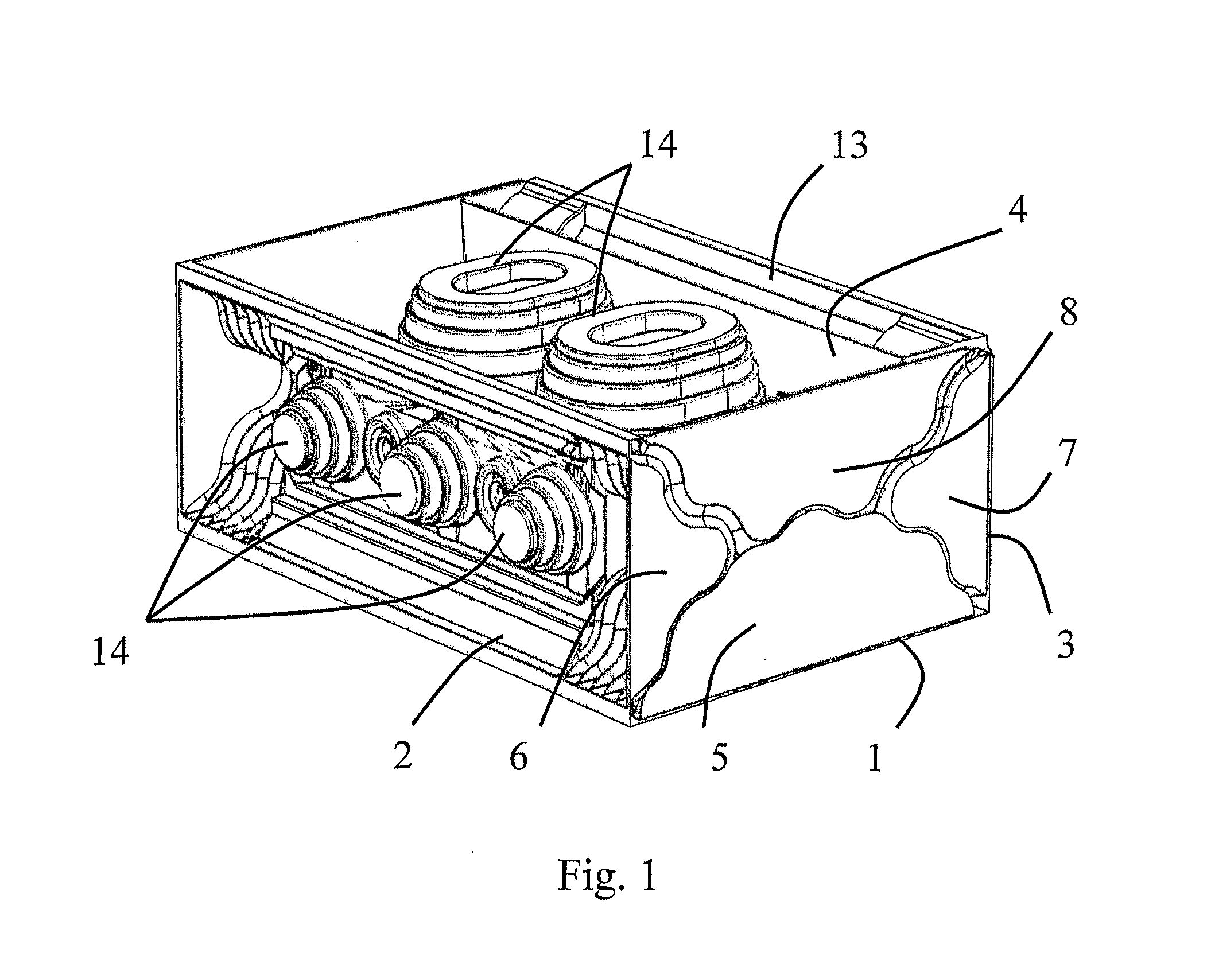
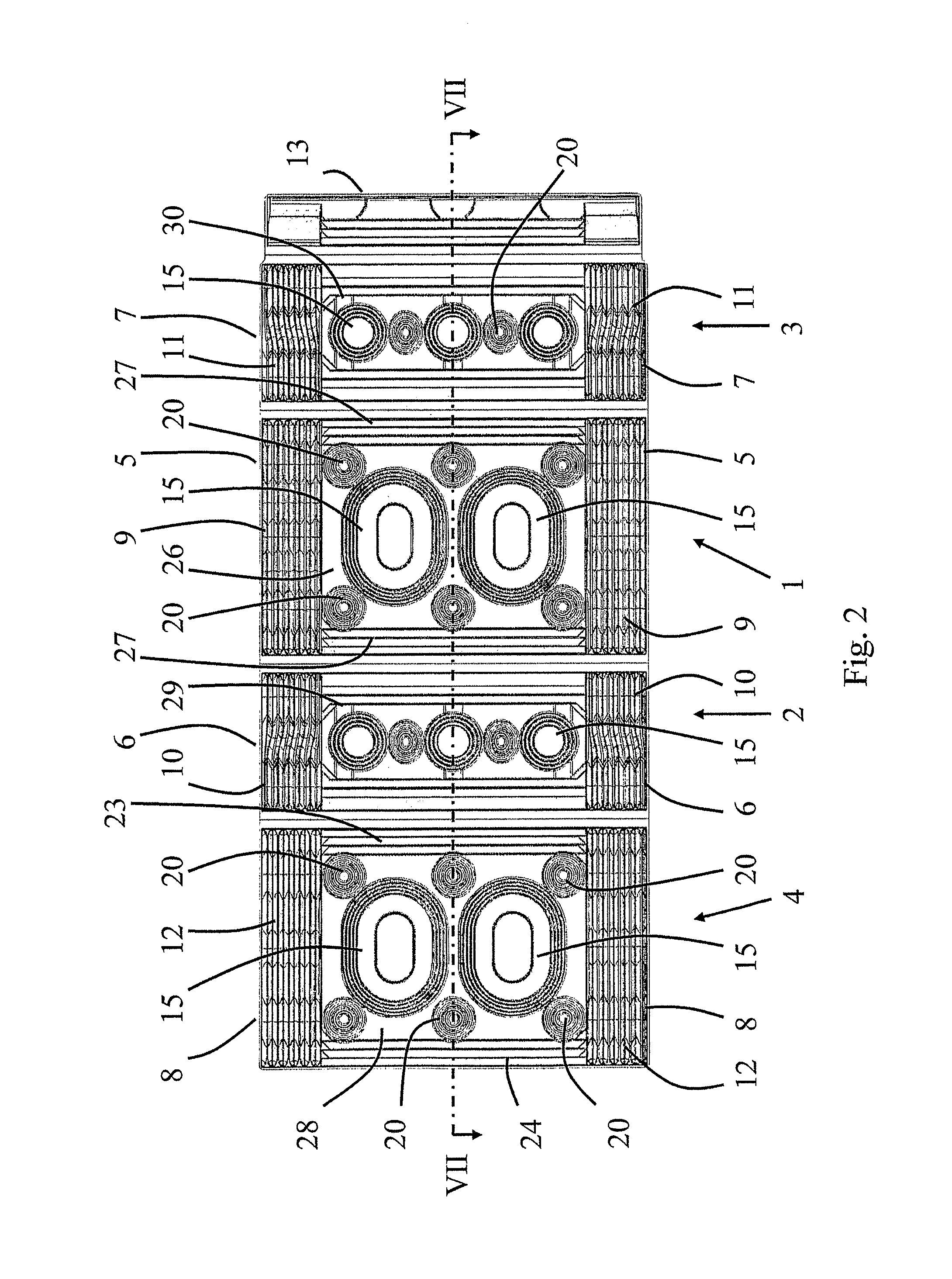
[0023]Referring to FIG. 1, the erected packaging case of this example is of elongate rectangular form, being erected from the one-piece thermoformed sheet (for example of polypropylene) shown in FIG. 2, by folding round the one or more articles (not shown) to be protected. In the latter respect, and referring also to FIG. 2, the case has four substantially-rectangular walls, namely, a base-wall 1, two opposite side-walls 2 and 3, and a top-wall 4, that are hinged together longitudinally. The walls 1 to 4 have flanges 5 to 8 respectively that are upstanding from their two ends. The upper edges of the flanges 5 to 8 at each end are configured with respective patterns 9 to 12 of ridges with intervening grooves running side-by-side with one another along the edge.

[0024]Erection of the case from the flat condition of FIG. 2 to the erect condition shown in FIG. 1, is brought about by folding the side-wall 2 up from the base-wall 1 and then folding the top-wall 4 down from the side-wall 2 ...


PUM


Abstract

A thermoformed packaging case has four wall-flanges which abut in ridge-within-groove nesting for interlocking and shock-absorbing closure of the case. Each edge has a pattern of ridges and grooves, and nesting of the edges of the flanges is enabled by a lateral shift in its ridge-groove pattern. Articles contained within the case are cushioned from shock by projections which protrude inwardly from inner surfaces of the walls to resiliently bear against the articles. Each buffer has a top surface surrounded by a valley and hump to provide shock-absorbing resilience. Locking of the case involves a flap hinged to a side-wall. To close a top-wall of the case onto the side-wall, projections of the top-wall enter recesses of the side-wall, and by folding the flap over to insert the projections into reverse recesses of the projections. The projections are snapped into recesses to effect triple-locking of the flap.

Description

[0001]This application is a National Stage completion of PCT / GB2009 / 002414 filed Oct. 9, 2009, which claims priority from British patent application serial no. 0818508.4 filed Oct. 9, 2008.FIELD OF THE INVENTION[0002]This invention relates to packaging and is concerned particularly with packaging for use in protecting articles against damage and shock during storage and transit.BACKGROUND OF THE INVENTION[0003]Various packaging methods have been used for protecting, for example electronic components, during storage and transit. These methods, in addition to being generally labor-intensive, commonly involve a substantial outlay in cost and material-resources on packaging items in the form, for example, of cardboard cases and specially-designed items of plastics foam and corrugated cardboard to fit within them.[0004]A form of packaging case that may be used with advantage environmentally and economically is described in GB-A-2414728. The rectangular packaging case described is of a th...

Claims


Application Information

Patent Timeline
Patent Type & Authority Applications(United States)
IPC IPC(8): B65D81/02
CPCB65D81/053B65D81/057B65D81/055B65D2581/055B65D21/023B65D81/02B65D81/05B65D81/113
Inventor PITT, JEFFREY GRAHAM
Owner PROTECTIVE PACKAGING SYST EUROPE BV
Why Eureka
Try Eureka