
Zoom lens and optical apparatus

a technology of optical apparatus and zoom lens, which is applied in the field of zoom lens, can solve problems such as optical performance deterioration, and achieve the effect of low optical performance deterioration sensitivity

Active Publication Date: 2011-10-06
CANON KK
View PDF4 Cites 8 Cited by
  • Summary
  • Abstract
  • Description
  • Claims
  • Application Information

AI Technical Summary

Benefits of technology

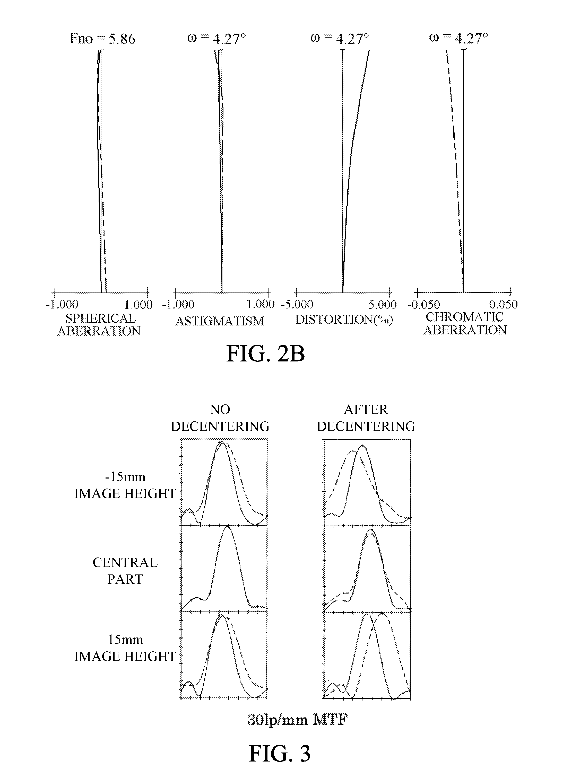
[0009]The present invention provides a zoom lens with a low optical performance deterioration sensitivity for the decentering of the first lens unit that is moved largely during the variation of magnification.

Problems solved by technology

The decentering of the first lens unit at which an axial ray height and an off-axis principal ray height are both large significantly affects optical performance of the zoom lens, in other words, easily causes optical performance deterioration.

Method used


Image

  • Zoom lens and optical apparatus
  • Zoom lens and optical apparatus
  • Zoom lens and optical apparatus

Examples


embodiment 1

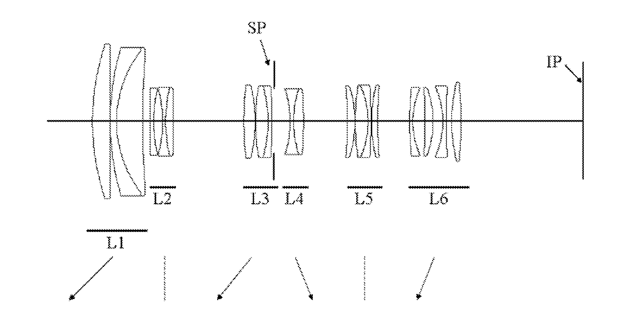
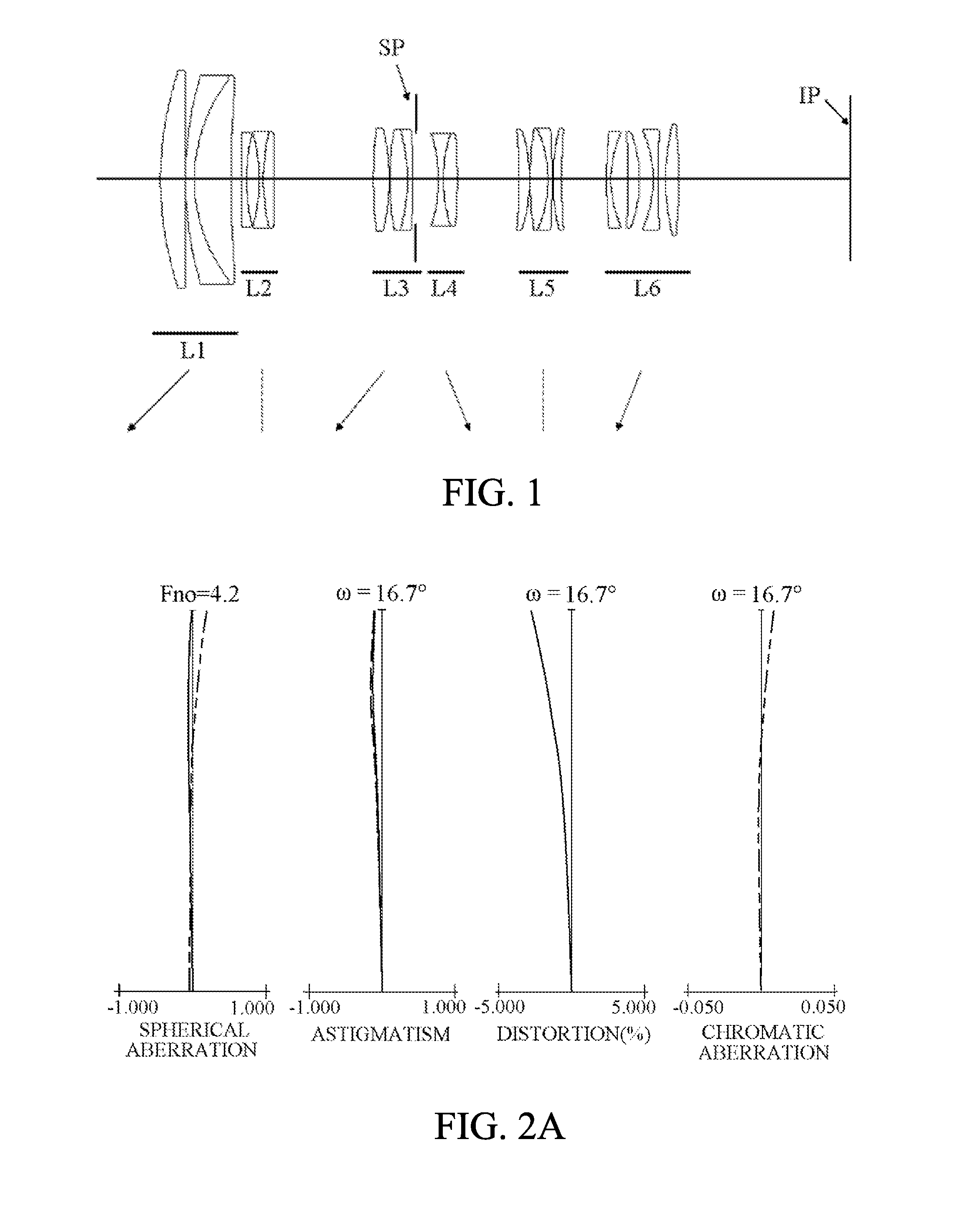
[0098]The zoom lens of Embodiment 1 (Numerical Example 1) shown in FIG. 1 includes, in order from the object side, the first lens unit L1 having a positive optical power, the second lens unit L2 having a negative optical power, a third lens unit L3 having a positive optical power, a fourth lens unit L4 having a negative optical power, a fifth lens unit L5 having a positive optical power and a sixth lens unit L6 having a negative optical power. The half field angle at the telephoto end is 4.2 degrees.

[0099]The first lens unit L1 is constituted by, in order from the object side, the positive lens, and a cemented lens formed by cementing the negative meniscus lens having the object side convex surface to the positive meniscus lens having the image side concave surface.

[0100]The zoom lens of this embodiment satisfies the condition (1) for the image side concave surface of the positive meniscus lens in the first lens unit L1. The satisfaction of the condition (1) brings the ray direction...

embodiment 2

[0107]The zoom lens of Embodiment 2 (Numerical Example 2) shown in FIG. 4 includes, in order from the object side, the first lens unit L1 having a positive optical power, the second lens unit L2 having a negative optical power, a third lens unit L3 having a positive optical power, a fourth lens unit L4 having a negative optical power, a fifth lens unit L5 having a positive optical power and a sixth lens unit L6 having a negative optical power. The half field angle at the telephoto end is 3.2 degrees.

[0108]The zoom lens of this embodiment satisfies the conditions (1)-(3) and the conditions (6)-(9). The second lens unit L2 having the negative optical power is unmoved during the zooming.

embodiment 3

[0109]The zoom lens of Embodiment 3 (Numerical Example 3) shown in FIG. 7 includes, in order from the object side, the first lens unit L1 having a positive optical power, the second lens unit L2 having a negative optical power, a third lens unit L3 having a negative optical power, a fourth lens unit L4 having a positive optical power and a fifth lens unit L5 having a negative optical power. The half field angle at the telephoto end is 4.2 degrees.

[0110]The zoom lens of this embodiment satisfies the conditions (1)-(3) and the conditions (6)-(9). The second lens unit L2 having the negative optical power is unmoved during the zooming.


PUM


Abstract

The zoom lens includes a first lens unit being disposed closest to an object and having a positive optical power, and at least one subsequent lens unit being disposed closer to an image than the first lens unit. The first lens unit is moved toward the object during variation of magnification from a wide-angle end to a telephoto end. The first lens unit is constituted by at least three lenses including a positive meniscus lens being disposed closest to the image among the at least three lenses and having an image side concave surface, and a negative lens being disposed on an object side next to the positive meniscus lens. A condition of 1.55<Rpi / f1<2.90 is satisfied where Rpi represent a curvature radius of the image side concave surface of the positive meniscus lens, and f1 represents a focal length of the first lens unit.

Description

BACKGROUND OF THE INVENTION[0001]1. Field of the Invention[0002]The present invention relates to a zoom lens used for optical apparatuses such as digital still cameras, video cameras and interchangeable lenses.[0003]2. Description of the Related Art[0004]High variable magnification zoom lenses whose focal lengths are largely variable are disclosed in Japanese Patent Laid-Open Nos. 2007-003600 and 04-186211. These zoom lenses constituted by at least five lens units including, in order from an object side, a first lens unit having a positive optical power and a second lens unit having a negative optical power. In these zoom lenses, in order to effectively provide a high variable magnification ratio, the first lens unit is largely moved toward an object in an optical axis direction during variation of magnification from a wide-angle end to a telephoto end.[0005]In such zoom lenses, in order to move the first lens unit smoothly, it is necessary to provide a play (hereinafter referred to...

Claims


Application Information

Patent Timeline
Patent Type & Authority Applications(United States)
IPC IPC(8): G02B15/14G03B19/12
CPCG02B15/173G02B15/14G02B27/0062G02B15/1461G02B15/145109
Inventor SUGITA, SHIGENOBU
Owner CANON KK
Learn More