Electrical Accessory and Method of Providing Same

a technology for accessories and electrical devices, applied in the direction of electrical apparatus casings/cabinets/drawers, instruments, machine supports, etc., can solve the problems of unable to physically couple the holder and the mp3 player, and the electric accessory designed to work with the apple ipod® mini mp3 player is not compatible with the ipod® mp3 player

Inactive Publication Date: 2011-10-20
BELKIN INT
View PDF3 Cites 51 Cited by
  • Summary
  • Abstract
  • Description
  • Claims
  • Application Information

AI Technical Summary

Problems solved by technology

A common problem with electrical accessories is that the accessories are designed to be compatible with only one or a very limited number of electrical devices.
That is, an electrical accessory designed to work with the Apple iPod® MP3 player is not compatible with the Apple iPod® Mini MP3 player, the Apple iTouch® MP3 player, the Research-in-Motion Blackberry® dev...

Method used


Image

  • Electrical Accessory and Method of Providing Same
  • Electrical Accessory and Method of Providing Same
  • Electrical Accessory and Method of Providing Same

Examples


first embodiment

[0076]FIGS. 3-5 illustrate an example of a system used to adjustably couple arm 121 to arm 122, according to the This system is merely exemplary and is not limited to the embodiments presented herein. The adjustable coupling system can be employed in many different embodiments or examples not specifically depicted or described herein.

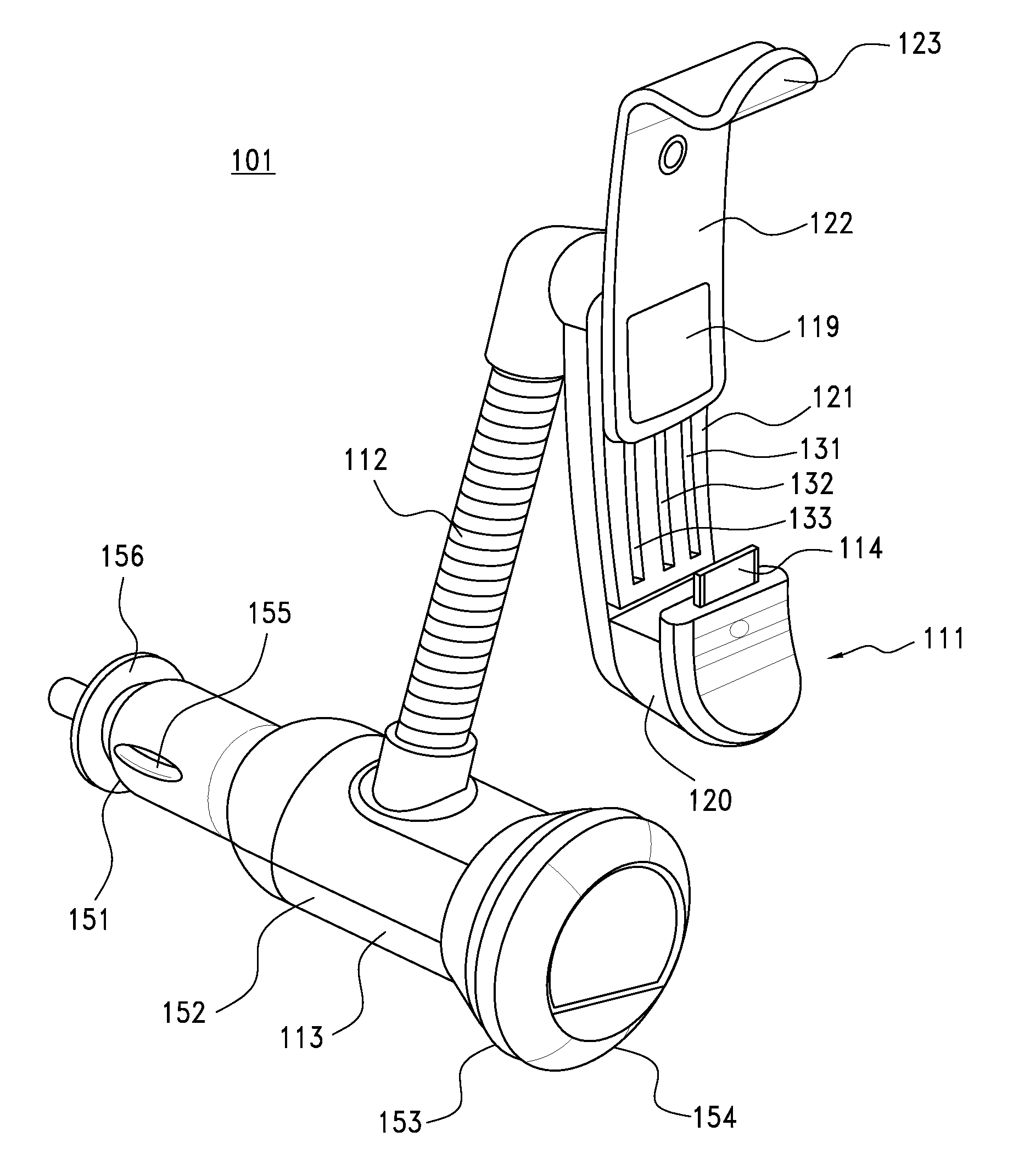
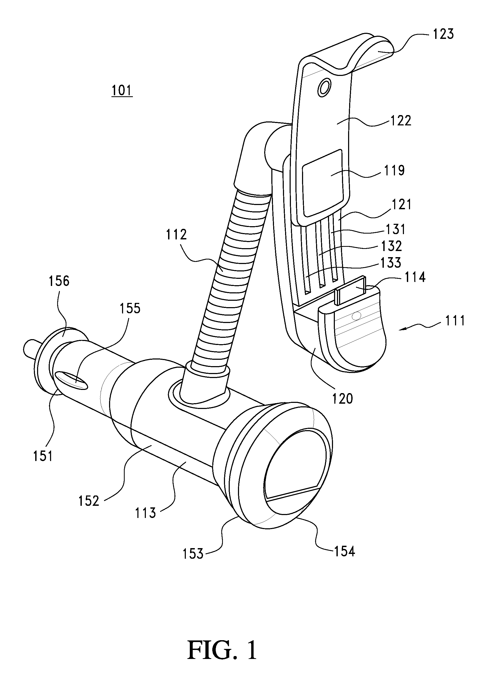
[0077]Referring to FIGS. 3-5, arm 121 can include one or more grooves 131, 132, and 133. Arm 122 can include: (a) protrusions 441, 442, 443, and 444; and (b) pins 445, 446, and 447. Protrusions 442 and 444 can be placed in groove 131. Protrusions 441 and 443 can be placed in groove 133. Pins 445, 446, and 447 can be placed into groove 132. The length of holder 111 can be adjusted by moving protrusions 441-444 and pins 445-447 in grooves 131-133. In some examples, protrusions 441-444 and pins 445-447 fit snugly to grooves 131-133 to secure arm 121 to arm 122.

[0078]Turning to another embodiment, FIG. 6 illustrates an isometric view of electrical accessor...

fourth embodiment

[0094]Aperture 1125 (FIG. 11) can be configured to securely integrated electrical interface 1214 into holder 1111. FIG. 14 illustrates an exploded view of an example of cradle section 1120 with electrical interface 1214 and wire 1235, according to the In this example, cradle section 1120 can include: (a) a first layer 1148; and (b) a second layer 1149 coupled to the top of first layer 1148. Cradle section 1120 can be configured with this two layer construction to securely and tightly hold electrical interface 1214.

[0095]In some examples, aperture 1125 can include: (a) an opening 1426 in second layer 1149; (b) a groove 1427 in second layer 1149 leading from an edge of second layer 1149 to opening 1426; and (c) a groove 1428 in first layer 1148. Grooves 1427 and 1428 can be sized such that a portion of wire 1235 can pass through grooves 1427 and 1428. Grooves 1427 and 1428 are not large enough to permit electrical interface 1214 to pass through or fit inside of grooves 1427 and 1428....

fifth embodiment

[0101]Turning to still another embodiment, FIG. 15 illustrates an isometric view of electrical accessory 1501, according to a As illustrated in FIG. 15, electrical accessory 1501 can include: (a) a holder 1511 configured to hold or couple to two or more electrical devices at different times; (b) a connector 1512; (c) a power acquisition unit 1513 configured to receive electrical power from an external power source (e.g., a cigarette lighter); (d) an electrical interface 1514 configured to mechanically and electrically couple to the two or more electrical devices at different times; and (e) a wire 1515 electrically and mechanically coupling electrical interface 1514 to power acquisition unit 1513. Electrical accessory 1501 is merely exemplary and is not limited to the embodiments presented herein. Electrical accessory 1501 can be employed in many different embodiments or examples not specifically depicted or described herein.

[0102]Holder 1511 can comprise: (a) a cradle section 1520 ...


PUM

PropertyMeasurementUnit
Lengthaaaaaaaaaa
Poweraaaaaaaaaa
Elasticityaaaaaaaaaa

Abstract

Some embodiments disclose a coupling device configured to couple to a surface. The coupling device including: (a) a first housing; (b) a rotational dial with a first aperture and mechanically coupled to the first housing, the rotational dial comprising a cam mechanism adjacent to the first aperture; (c) a support base comprising a first stem with a second aperture, the first stem is located inside the first aperture, the stem having a second aperture; (d) a suction cup coupled to at least one of the rotational dial or the support base, the suction cup having: (1) a suction portion; and (2) a second stem located inside of the second aperture; and (e) an elastic mechanism located at least partially between the support base and the second stem of the suction cup. The coupling device is configured such that the suction cup can be rotated relative to at least the rotational dial to create a vacuum between the suction portion and the surface. Other embodiments are disclosed herein.

Description

CROSS-REFERENCE TO RELATED APPLICATIONS[0001]This application is a continuation-in-part of U.S. patent application Ser. No. 12 / 545,017, filed Aug. 20, 2009, which is continuation of U.S. patent application Ser. No. 12 / 349,505, filed Jan. 6, 2009. U.S. patent application Ser. No. 12 / 349,505 is a continuation-in-part of U.S. patent application Ser. No. 10 / 936,356, now U.S. Pat. No. 7,292,881, filed Sep. 8, 2004 and a continuation-in-part of U.S. patent application Ser. No. 11 / 248,762, now U.S. Pat. No. 7,734,256, filed Oct. 11, 2005.[0002]This application is also continuation-in-part of U.S. patent application Ser. No. 12 / 171,220, filed Jul. 10, 2008, which is a continuation of U.S. patent application Ser. No. 11 / 842,921, filed Aug. 21, 2007, which is a continuation of U.S. patent application Ser. No. 10 / 936,356, now U.S. Pat. No. 7,292,881, filed Sep. 8, 2004. U.S. patent application Ser. No. 12 / 171,220 also claims priority from U.S. Provisional Application No. 60 / 959,057, filed Jul....

Claims


Application Information

Patent Timeline
IPC IPC(8): H05K7/00F16M13/00B23P11/00F16B47/00
CPCB60R11/02B60R2011/0005B60R2011/0007B60R2011/0054B60R2011/0075B60R2011/008Y10T29/49826H04B1/3822H04B1/3877H04M1/6075H04M1/6091F16M13/02H04B1/38
Inventor DUNCAN SEIL, OLIVERRAZO, VINCENTNEU, THORBENDEJONG, CHADKLEEMAN, DAVID A.NALWAD, VIJENDRAPARK, JUNGMANLANE, STEVEN
Owner BELKIN INT
Why Eureka
Try Eureka