Supercharge Your Innovation With Domain-Expert AI Agents!

Turbine engine with enhanced fluid flow strainer system

a turbine engine and strainer technology, applied in the direction of membrane technology, separation process, filtration separation, etc., can solve the problems of limiting the tuning effectiveness of burners, the size of the strainer holes b>16/b> does not appear to appreciably control the effective flow area of the holes, and the inability to remove unwanted particles

Inactive Publication Date: 2011-11-03
SIEMENS ENERGY INC
View PDF20 Cites 16 Cited by
  • Summary
  • Abstract
  • Description
  • Claims
  • Application Information

AI Technical Summary

Benefits of technology

"The invention is about a system for straining the flow of fluid in a turbine engine. The system includes a fluid supply conduit and a strainer. The strainer has a hollow body with a plurality of holes, and it is placed in the fluid supply conduit. The strainer is designed to partially block the flow of fluid in the conduit, creating a flow area that is equal to or greater than the flow area of the strainer's holes. This results in a reduced flow area, which can help to improve the performance of the turbine engine. The strainer can be located in different parts of the fluid supply conduit, and it can be sized to fit different diameters of the conduit. The system can help to improve the flow of fluid in the turbine engine and to reduce the likelihood of blockages."

Problems solved by technology

Such undesired particles may enter the fuel supply passages due to impurities or contaminants in the fuel itself and / or due to debris entering the fuel passage after manufacturing of the combustor.
Indeed, based on calculations, the size of the strainer holes 16 do not appear to appreciably control the effective flow area of the holes.
Supply pressure calculations with the new strainer designs have revealed that the drop in fuel supply pressure may limit the range of fuel splits that can be implemented at base load, which, of course, may limit the tuning effectiveness of the burners.

Method used


Image

  • Turbine engine with enhanced fluid flow strainer system
  • Turbine engine with enhanced fluid flow strainer system
  • Turbine engine with enhanced fluid flow strainer system

Examples


Embodiment Construction

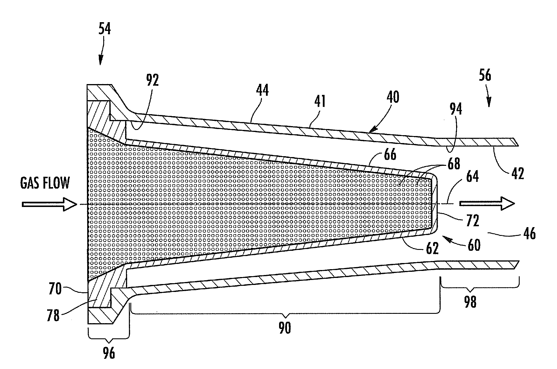
[0027]Embodiments of the invention are directed to strainer systems for use in fluid flows. Aspects of the invention will be explained in connection with a fuel delivery system for a turbine engine, but the detailed description is intended only as exemplary. Indeed, it will be appreciated that aspects of the invention can be applied to other areas of a turbine engine in which there is a fluid flow as well as in other applications. Embodiments of the invention are shown in FIGS. 3-4, but the present invention is not limited to the illustrated structure or application.

[0028]It is suspected that the outer peripheral surface of the strainer may be too close to the inner peripheral surface of the fuel supply pipe. In such area, the flow area defined between the outer peripheral surface of the strainer and the inner peripheral surface of the fluid supply pipe is less than the effective area of the strainer holes. As a result, there can be restrictions in the flow exiting the fuel strainer...


PUM

PropertyMeasurementUnit
diameteraaaaaaaaaa
diameteraaaaaaaaaa
radiusaaaaaaaaaa

Abstract

A fuel delivery system for a turbine engine includes a fluid supply conduit. The conduit has an inner peripheral surface that defines a flow supply passage. A fuel strainer is received in the conduit. The strainer has a hollow, generally frusto-conical body with an outer peripheral surface. The strainer has a longitudinal axis. A plurality of holes extends through the body substantially radially to the longitudinal axis. The holes have an associated effective flow area. The outer peripheral surface of the body is radially spaced from the inner peripheral surface of the conduit along the length of the strainer such that a flow area is defined between the outer peripheral surface of the strainer body and the inner peripheral surface of the fluid supply conduit. The flow area is equal to or greater than the effective flow area of the strainer holes along the length of the strainer.

Description

FIELD OF THE INVENTION[0001]The invention relates in general to turbine engines and, more particularly, to fuel delivery systems in a turbine engine.BACKGROUND OF THE INVENTION[0002]A typical turbine engine has a compressor section, a combustor section and a turbine section. During engine operation, air can be inducted into the compressor section and compressed. The compressed air can enter the combustor section where it can be mixed with fuel. The air-fuel mixture is ignited to form a high temperature working gas, which is routed to the turbine section.[0003]Fuel can be delivered at various points in the combustor section by way of fuel supply passages. A strainer can be positioned within such fuel supply passages. The strainer can be used to remove particles that could potentially clog the fuel injection outlet holes. Such undesired particles may enter the fuel supply passages due to impurities or contaminants in the fuel itself and / or due to debris entering the fuel passage after...

Claims


Application Information

Patent Timeline
Patent Type & Authority Applications(United States)
IPC IPC(8): B01D35/28
CPCB01D29/35B01D35/02B01D2275/201B01D2201/02B01D46/2403
Inventor RYAN, WILLIAM R.
Owner SIEMENS ENERGY INC
Features
  • R&D
  • Intellectual Property
  • Life Sciences
  • Materials
  • Tech Scout
  • Unparalleled Data Quality
  • Higher Quality Content
  • 60% Fewer Hallucinations
Learn More