Coupling

a technology of coupling and fluid, applied in the field of coupling, can solve the problems of failure of the joint or bending of the arm, the failure the excessive force of the closing mechanism and its arms, so as to achieve the effect of optimal force taking, simple and efficient manner, and simplifying the engagement and disengagemen

Inactive Publication Date: 2011-11-10
CEJN
View PDF10 Cites 6 Cited by
  • Summary
  • Abstract
  • Description
  • Claims
  • Application Information

AI Technical Summary

Benefits of technology

[0003]The present invention intends to avoid the problems of excessive force on the arms and joints of the closing mechanism of the coupling, when the nipple and socket are fully engaged and the system is fully pressurized creating a force tending to separate the nipple from the socket. This is achieved by a high pressure fluid coupling assembly of the type described by way of introduction which has the characterizing features given in claim 1. An assembly of this type provides a secure locking of the nipple in the socket. According to a preferred embodiment the load, when the coupling is under pressure, is transferred from the closing mechanism to the locking plate and the distributed guide bolts. According to other preferred embodiments of the invention, the locking plate is engaged with the narrower neck portions of the guide bolts in a particularly simple, efficient and effective manner, simplifying engagement and disengagement and providing optimal taking up of the forces tending to separate the nipple from the socket when the system is under high fluid pressure. The preferred embodiments allow the closing mechanism to be dimensioned in a less bulky and more functional manner since the closing mechanism and its joints will not be subjected to excessive forces when the system is fully pressurized.

Problems solved by technology

High pressure fluid couplings when closed usually are subjected to extreme forces on the closing mechanism and its arms during use.
This puts enormous forces on the arms and joints of the closing mechanism resulting either in failure in the joints or bending of the arms or extremely bulky dimensioning of the arms and joints.

Method used


Image

  • Coupling
  • Coupling
  • Coupling

Examples


Embodiment Construction

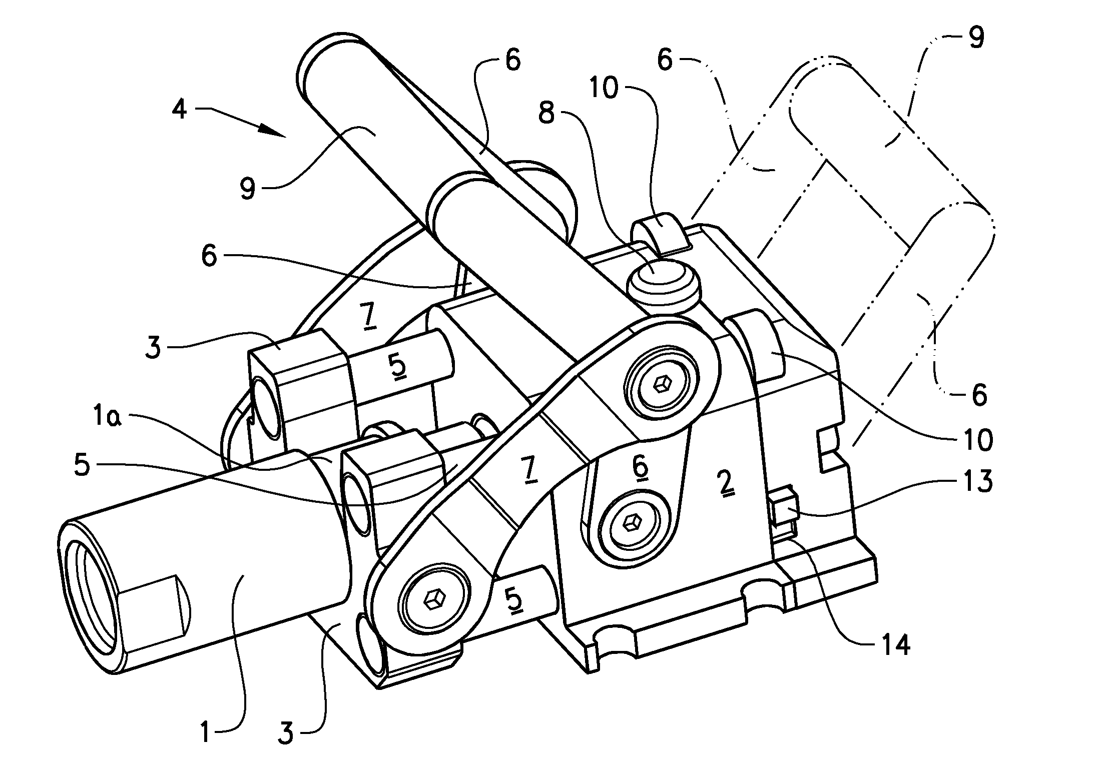
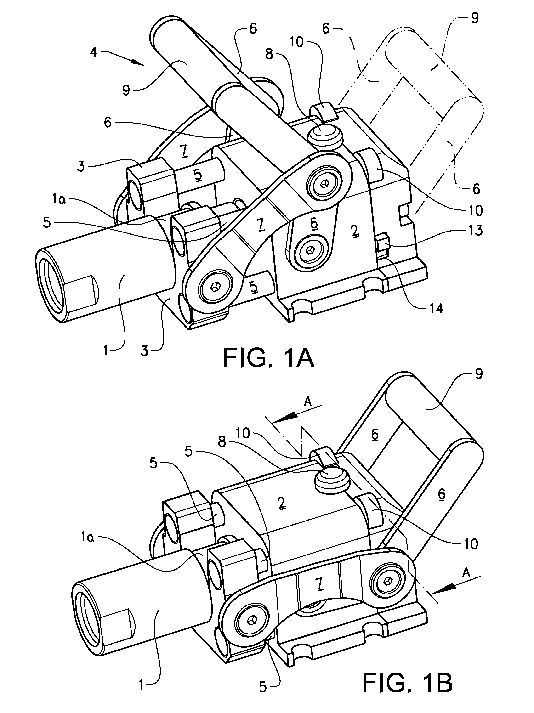
[0011]The invention will be described with reference here to a single non-limiting illustrative example, where the same reference numerals are used for the same parts in the various views.

[0012]FIG. 1A shows a fluid coupling according to the invention where a typical fluid coupling nipple 1 on a hose (not shown) has been placed with its neck 1 a of smaller diameter in a yoke 3 having a slot of minimally larger inner diameter than the diameter of the neck 1a. A socket box 2 connects to a further hydraulic line (not shown in FIGS. 1-2). The yoke 3 has four guide bolts 5 symmetrically distributed about the central axis of the assembly. The four guide bolts 5 extend through the box 2. The nipple 1 held in the yoke 3 is moved to its fully coupled state by pulling the lever 6 of the mechanism 4 to the right as shown in the figures to the position shown in FIG. 1B, with the yoke 3 retracted against the box 2. The connecting arm 7 between the lever 6 and the yoke 3 will be in a horizontal p...


PUM


Abstract

A high pressure fluid coupling assembly comprises a nipple (1) with a neck 1 a to be held in a yoke 3, which is pulled towards a socket box 2 by a lever mechanism 4. When the nipple is pulled into complete engagement with the socket, the final downward movement of the lever 6 pushes a locking plate 10 into locking engagement with the distal ends of guide bolts 5, evenly distributed about the nipple and extending from the yoke and sliding through the socket box 2 to the locking plate 10, which is in contact 10 with the side of the socket box 2 facing 13 away from the yoke. The locking plate 10, guide bolts 5, yoke 3 and socket box 2 take up the nipple/socket separating force generated by the very high hydraulic pressure instead of the arms and joints of the lever mechanism 4.

Description

TECHNICAL FIELDBackground Art[0001]High pressure fluid couplings when closed usually are subjected to extreme forces on the closing mechanism and its arms during use. Demolition machines, hydraulic hammers and mining machines often use large diameter hoses (≧1″=26 mm) and routinely develop pressures of up to 350 bar during use. This puts enormous forces on the arms and joints of the closing mechanism resulting either in failure in the joints or bending of the arms or extremely bulky dimensioning of the arms and joints.SUMMARY OF THE INVENTION[0002]The present invention relates to a high pressure fluid coupling assembly of the type described in the preamble to the accompanying claim 1.[0003]The present invention intends to avoid the problems of excessive force on the arms and joints of the closing mechanism of the coupling, when the nipple and socket are fully engaged and the system is fully pressurized creating a force tending to separate the nipple from the socket. This is achieved...

Claims


Application Information

Patent Timeline
Patent Type & Authority Applications(United States)
IPC IPC(8): F16L37/14F16L35/00F16L37/20
CPCE02F3/966E02F9/2275F16L37/20F16L37/142F16L37/56F16L23/003F16L37/14F16L55/00
Inventor BOHMAN, PETER
Owner CEJN
Why Eureka
Try Eureka