
Stepping motor

a technology of stepping motor and stator yoke, which is applied in the direction of dynamo-electric machines, magnetic circuit shapes/forms/construction, master clocks, etc., can solve the problems of increasing the number of working steps and the inability to reduce the production cost of welding, so as to prevent cost-cutting and size reduction, improve the lack of consistency in characteristics, and improve the effect of quality

Active Publication Date: 2011-11-24
MINEBEAMITSUMI INC
View PDF6 Cites 3 Cited by
  • Summary
  • Abstract
  • Description
  • Claims
  • Application Information

AI Technical Summary

Benefits of technology

[0006]As a method for improvement in the lack of consistency in characteristics of a stepping motor, the welding disclosed in Japanese Patent Application, First Publication No. 2002-112522, and the additional reinforcing board to a magnetic circuit which is disclosed in Japanese Patent Application, First Publication No. 2007-143253, may be used. However, the welding increases the number of working steps, so that producing cost cannot be reduced in the welding. Furthermore, the additional reinforcing board to the magnetic circuit in Japanese Patent Application, First Publication No. 2007443253 increases the number of parts, so that cost-cutting and reductions in size are prevented. In such circumstances, an object of the present invention is to provide a stepping motor in which a contacting condition of fixing portions of an outer and an inner yokes can be improved without increase in number of working steps and number of parts, and lack of consistency of characteristics of the motor can be inhibited.
[0008]According to the first aspect of the present invention, the fixed portion of the inner and the outer yoke is positioned at the axial inside maintaining a distance from an opening end of the cup shape of the outer yoke. Therefore, a phenomenon in which the opening end of the cup shape of the outer yoke affects a magnetic circuit in the yoke can be avoided.
[0010]According to a third aspect of the present invention, in the second aspect, the fixed portion is positioned at the position avoiding the round portion. According to the third aspect of the present invention, the inner yoke is fixed with respect to the outer yoke at the position except for the round portion, so that the effect of the unevenness of the condition of the round portion with respect to the fixing condition between the outer and the inner yokes can be avoided.
[0012]According to the first aspect of the present invention, a stepping motor, in which the contacting condition between the outer and the inner yokes can be improved without increase in working steps and number of parts and unevenness of characteristics of the motor can be inhibited, can be provided.

Problems solved by technology

However, the welding increases the number of working steps, so that producing cost cannot be reduced in the welding.

Method used


Image

  • Stepping motor
  • Stepping motor
  • Stepping motor

Examples


Embodiment Construction

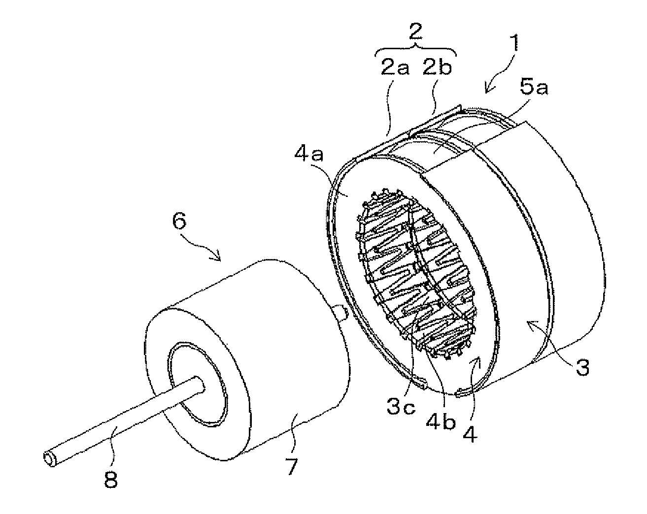
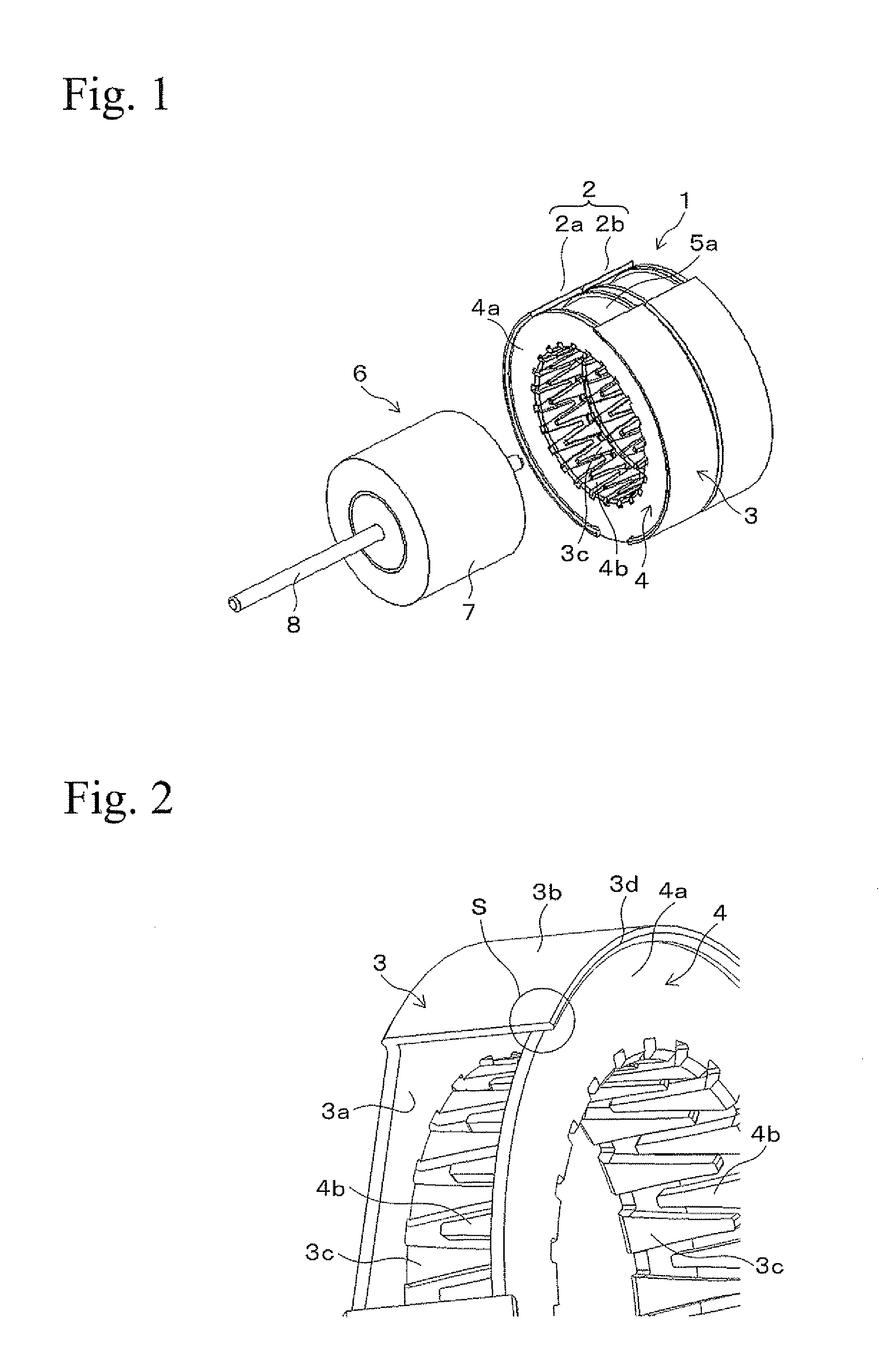
[0022]A claw-pole-type stepping motor 1 according to an embodiment is shown in FIG. 1. A partially enlarged condition of a structure of the stepping motor 1 is shown in FIG. 2. The structure in which an outer portion is partially cut away in order to show the inside is shown in the drawing in FIG. 2. The stepping motor 1 is provided with a stator 2. The stator 2 is provided with stators 2a and 2b that have two phases and are axially adjoined. The structures of stators 2a and 2b are the same.

[0023]The stator 2a is selectively explained hereinafter. The stator 2a has a structure in which an inner yoke 4 is axially combined and fixed to a cup-shaped outer yoke 3 and an outer circumferential portion of the outer yoke 3 is wound around by a coil 5a functioning as a stator coil.

[0024]The outer yoke 3 has a cup shape that is open toward an axially one-way direction. That is, as shown in FIG. 2, the outer yoke 3 is provided with a bottom surface portion 3a having an annular shape and an out...


PUM


Abstract

A claw-pole-type stepping motor includes a stator annularly disposed therein and having a coil, a rotor rotatably disposed inside the stator and having a multiply magnetized permanent magnet and a shaft, an outer yoke provided in the stator and having a cup shape opening toward an axially outside direction an outer circumferential portion provided in the outer yoke and having a cylindrical shape and an inner circumferential portion including first pole teeth, an inner yoke provided in the stator and having second pole teeth provided in an inner circumference thereof and an outer circumferential portion fixed to an inner circumferential surface of the outer circumferential portion of the outer yoke, in which the first pole teeth and the second pole teeth are engaging with each other via a gap in an axial direction and are disposed with respect to the permanent magnet of the rotor via a gap, a fixed portion of the inner yoke and the outer yoke is positioned at the axial inside of an opening end of the cup shape of the outer yoke and the opening end protrudes beyond the fixed portion toward the axially outer direction.

Description

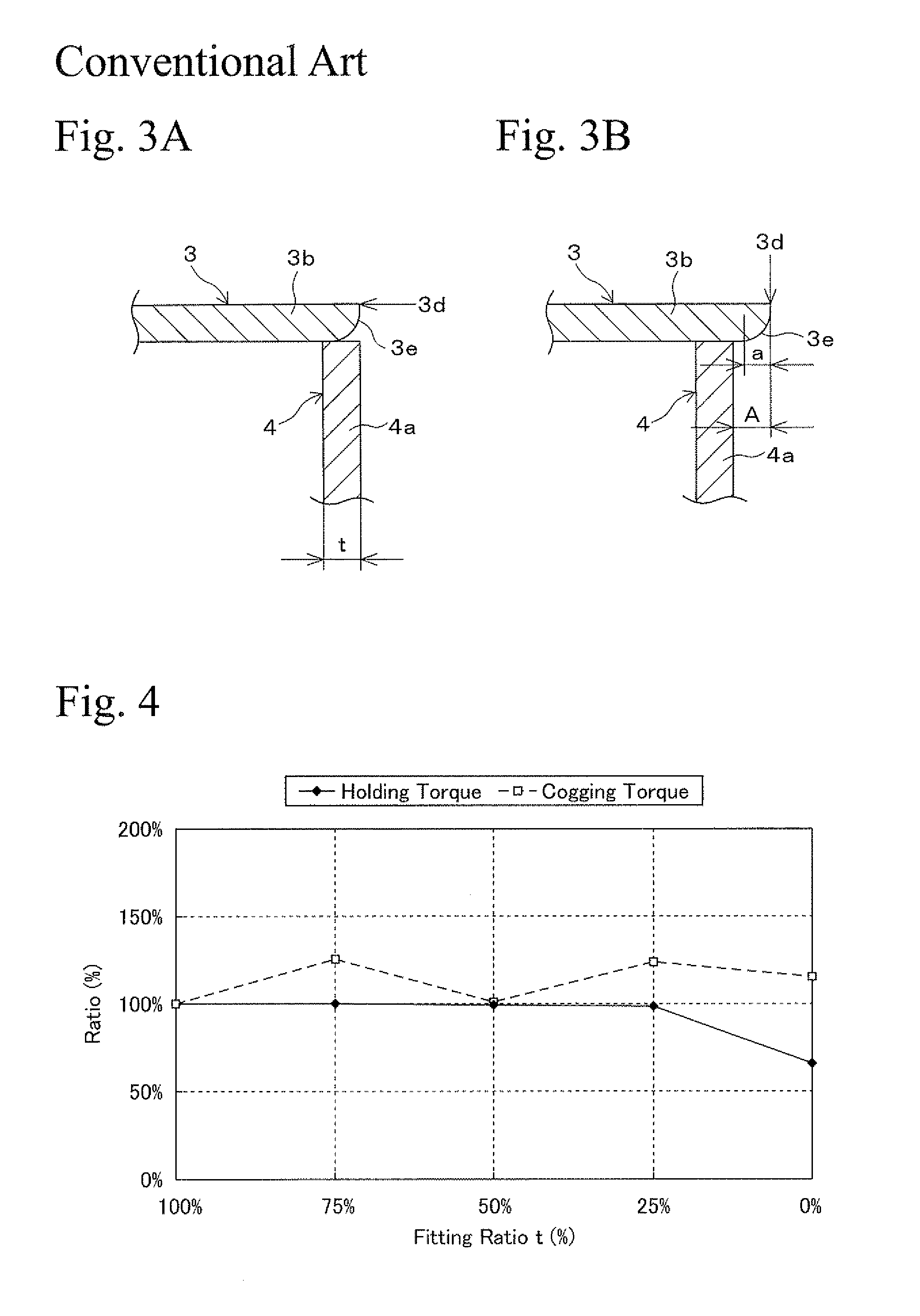
BACKGROUND OF THE INVENTION[0001]1. Field of the Invention[0002]The present invention relates to a structure of a stator yoke of a stepping motor.[0003]2. Related Art[0004]In a claw-pole-type stepping motor, when an outer yoke is fixed to an inner yoke, a method such as press fitting, caulking, bonding and welding between an inside of the cup-shaped outer yoke and an outer circumferential portion of the inner yoke contacting the inside of the outer yoke, is used. However, the outer and inner yokes are produced by press working, so that a round portion is formed by bending at a cup-shaped opening side end portion which is a fixing portion for the outer yoke and a material flow is formed by punching at the outer circumference that is a fixing portion for the inner yoke. In this condition, when the fixing portions of the inner and outer yokes are contacted on the same plane, the contacting area is uneven according to conditions of the round portions caused by bending and material flow ...

Claims


Application Information

Patent Timeline
Patent Type & Authority Applications(United States)
IPC IPC(8): H02K37/14
CPCH02K1/145H02K2213/03H02K37/14
Inventor KINPARA, SHUHEISUZUKI, YUZURUFUJIMOTO, SEIYA
Owner MINEBEAMITSUMI INC
Learn More