Eureka AIR delivers breakthrough ideas for toughest innovation challenges, trusted by R&D personnel around the world.

Enclosure of electronic device

Inactive Publication Date: 2011-12-08
HONG FU JIN PRECISION IND (SHENZHEN) CO LTD +1
View PDF2 Cites 8 Cited by
  • Summary
  • Abstract
  • Description
  • Claims
  • Application Information

AI Technical Summary

Problems solved by technology

These enclosures may define a lot of heat dissipating holes to dissipate the heat in the enclosures.
However, if the heat dissipating holes are very small, the heat dissipating effect is not desirable.
If the heat dissipating holes are very big, dust and other contaminants will easily enter the enclosures.

Method used


Image

  • Enclosure of electronic device
  • Enclosure of electronic device
  • Enclosure of electronic device

Examples


Embodiment Construction

The disclosure, including the accompanying drawings, is illustrated by way of example and not by way of limitation. It should be noted that references to “an” or “one” embodiment in this disclosure are not necessarily to the same embodiment, and such references mean at least one.

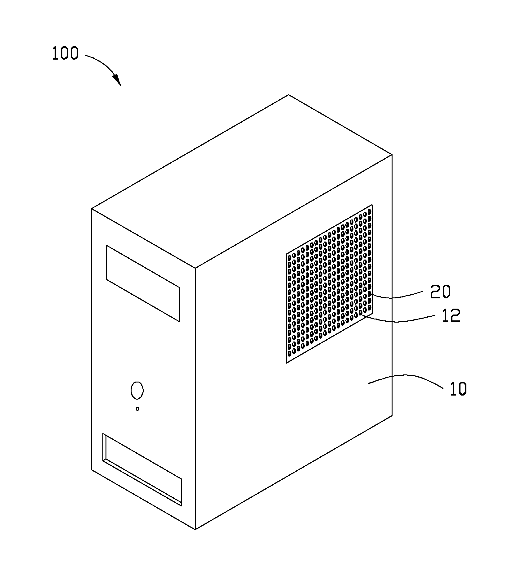
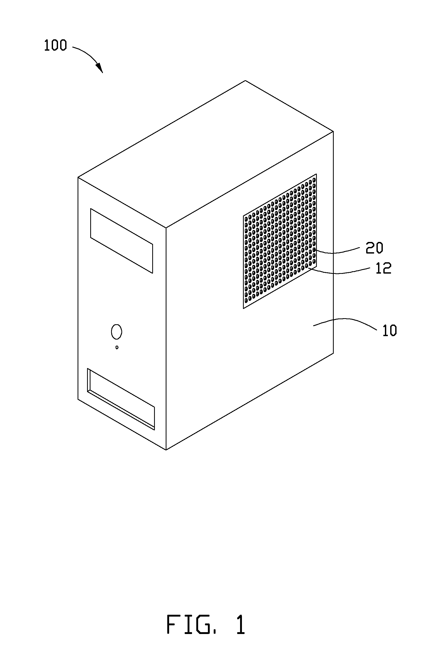
Referring to FIG. 1, an embodiment of an enclosure 100 includes a case 10 and a heat dissipating area 12 formed on the case 10. The heat dissipating area 12 defines a plurality of heat dissipating holes 20 therein.

In one embodiment, the heat dissipating holes 20 are round and evenly arrayed in the heat dissipating area 12. In other embodiments, the shape of the heat dissipating holes 20 can be changed according to requirements. The material of the heat dissipating area 12 is thermo-responsive shape memory polymer (SMP).

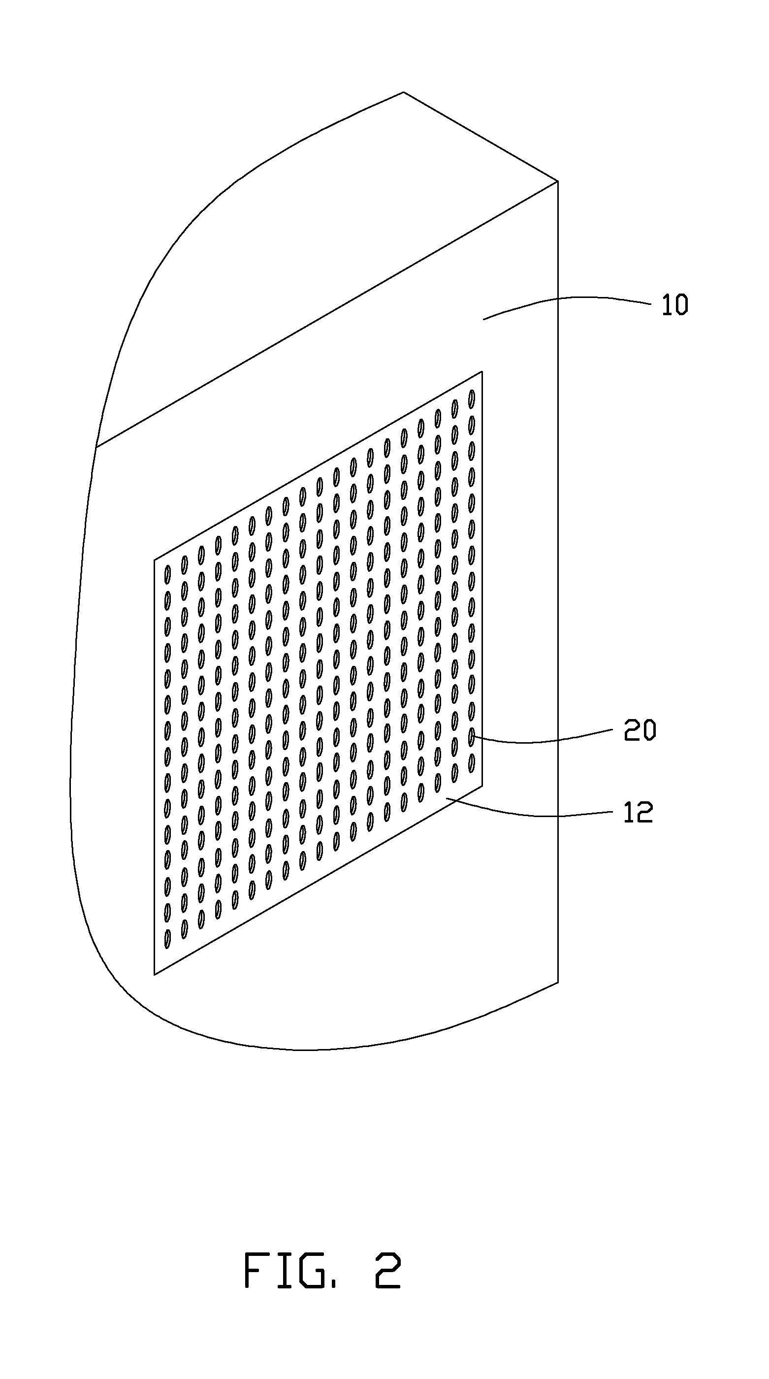
FIG. 2 shows a first state of the enclosure 100 when the temperature around the heat dissipating area 12 is under a predetermined value, such as 40 degrees Celsius. FIG. 3 shows a second state...


PUM


Abstract

An enclosure includes a case and a heat dissipating area formed on the case. The heat dissipating area defines a number of heat dissipating holes in the heat dissipating area. The material of the heat dissipating area is thermo-responsive shape memory polymer. The heat dissipating holes have a first size in response to the temperature around the heat dissipating area being under a predetermined value. The heat dissipating holes can grow to a second size in response to the temperature around the heat dissipating area being greater than the predetermined value. The first size is less than the second size.

Description

BACKGROUND1. Technical FieldThe present disclosure relates to an enclosure of an electronic device.2. Description of Related ArtMost electronic devices have enclosures to contain electronic elements. These enclosures may define a lot of heat dissipating holes to dissipate the heat in the enclosures. However, if the heat dissipating holes are very small, the heat dissipating effect is not desirable. If the heat dissipating holes are very big, dust and other contaminants will easily enter the enclosures.BRIEF DESCRIPTION OF THE DRAWINGSMany aspects of the present embodiments can be better understood with reference to the following drawings. The components in the drawings are not necessarily drawn to scale, the emphasis instead being placed upon clearly illustrating the principles of the present embodiments. Moreover, in the drawings, all the views are schematic, and like reference numerals designate corresponding parts throughout the several views.FIG. 1 is an isometric, schematic vie...

Claims


Application Information

Patent Timeline
IPC IPC(8): F28F9/00
CPCG06F1/181G06F1/20H05K7/20209H05K7/20181H05K7/20127
Inventor ZHOU, YAN-LI
Owner HONG FU JIN PRECISION IND (SHENZHEN) CO LTD
Why Eureka
Eureka Blog
Learn More