
Protective guard for needles of injection devices having removable needle assemblies

a technology of protective guards and injection devices, which is applied in the direction of injection needles, intravenous devices, infusion devices, etc., can solve the problems of many countermeasures introducing annoying drawbacks, affecting the safety of medical personnel, and causing personnel to drop or otherwise mishandle equipmen

Inactive Publication Date: 2011-12-29
CHUN THOMAS
View PDF25 Cites 43 Cited by
  • Summary
  • Abstract
  • Description
  • Claims
  • Application Information

AI Technical Summary

Benefits of technology

"The present invention provides a self-deploying cover assembly for exposed needles and the like. The cover is a self-contained device that can be installed on various injection devices such as syringes or autoinjectors. The cover is designed to immobilize the injection device in an initial position and lock over the needle after the injection is done. The cover is easy to install, economical, and effective in preventing accidental pricks. The invention allows for the reuse of the injection device and its associated plunger, reducing waste. The cover can be used as a modular accessory to the injection device."

Problems solved by technology

This presents a hazard to medical personnel due to unintended pricking of the personnel's body.
This can be uncomfortable, can cause the personnel to drop or otherwise mishandle equipment, and most of all, threatens to transfer contaminants from an injected person's blood to the medical personnel.
However, many countermeasures introduce annoying drawbacks.
This may for example oblige medical personnel to put down other equipment and objects and perform the necessary installation or removal, or otherwise interfere with expeditious performance of medical tasks.

Method used


Image

  • Protective guard for needles of injection devices having removable needle assemblies
  • Protective guard for needles of injection devices having removable needle assemblies
  • Protective guard for needles of injection devices having removable needle assemblies

Examples


Embodiment Construction

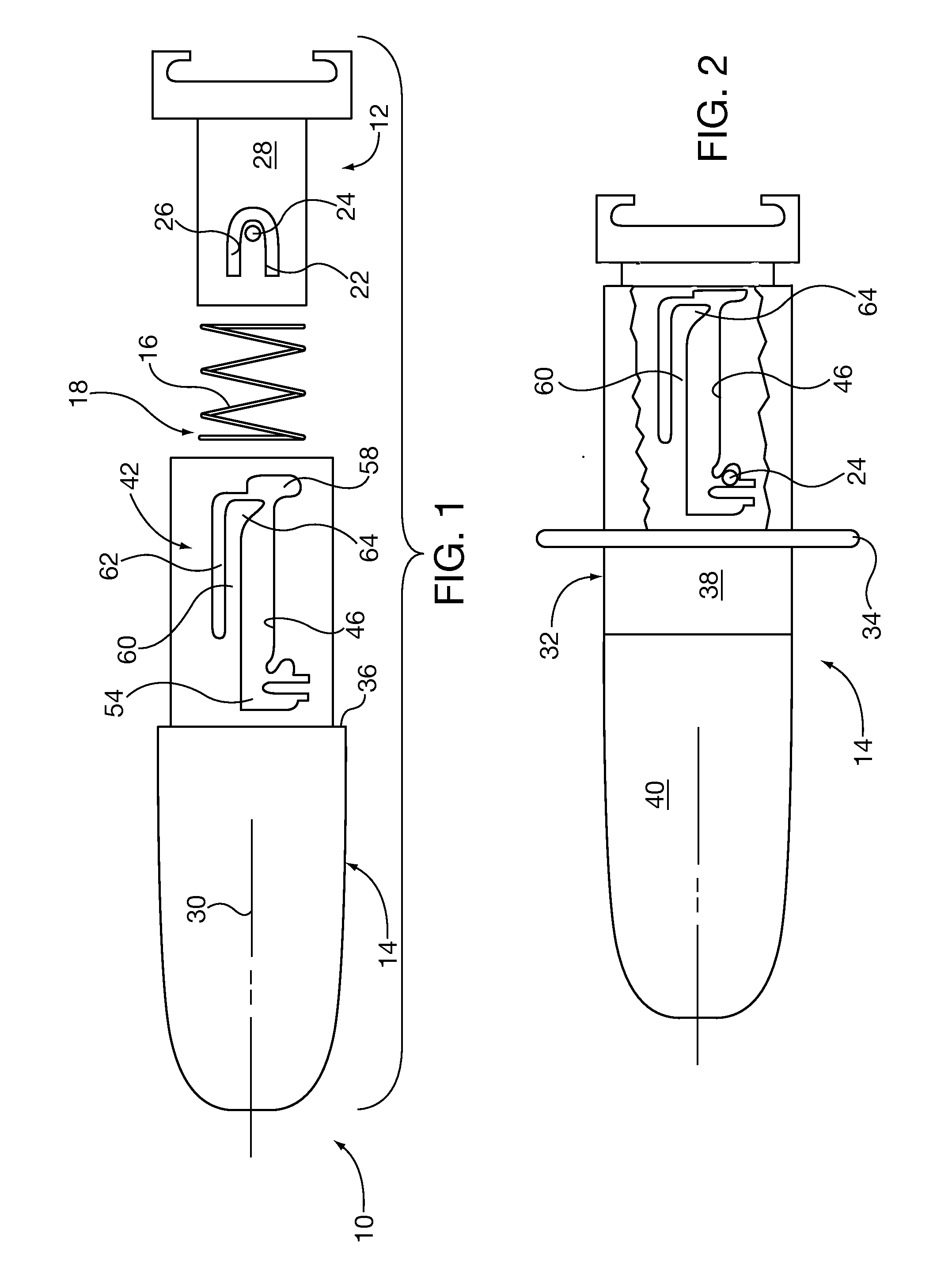
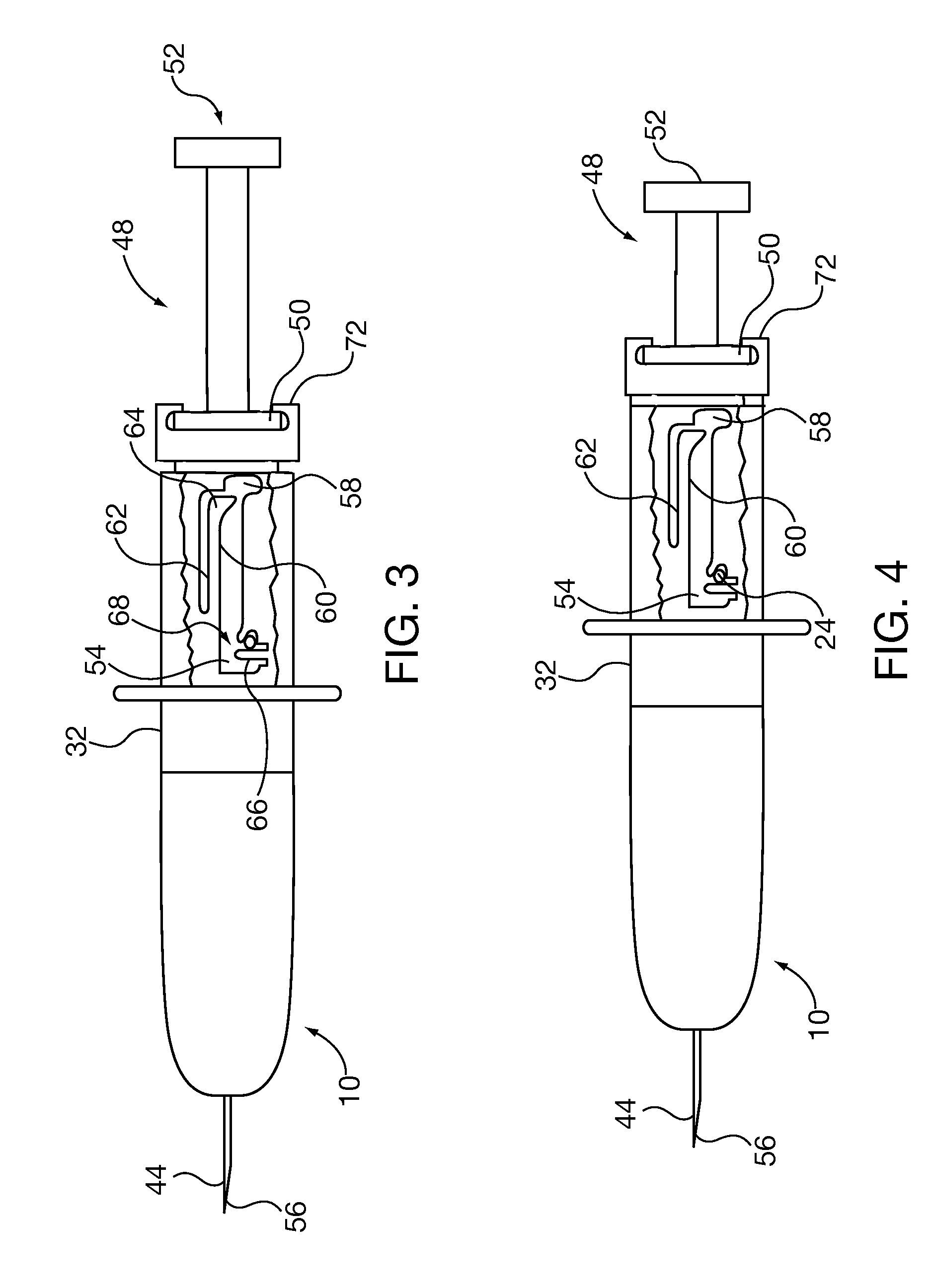
[0024]Referring first to FIG. 1, according to at least one aspect of the invention there is shown components of a self-deploying protective cover 10, without its associated injection device 12 (which will be seen in FIG. 3). The self-deploying cover 10 may comprise a base 12, a protective sleeve 14, and a coil spring 16. The protective sleeve 14 may have an open interior 18 adapted to interfit telescopingly with the base 12. That is, the open interior 18 may be dimensioned and configured to slidably receive the base 12 in close cooperation therewith.

[0025]The base 12 is seen to have a finger 22 bearing a projection 24. The finger 22 is defined by a U-shaped channel 26 formed in the wall 28 of the base 12. The projection 24 projects outwardly from the finger 22. Projection in the outward direction will be understood to be away from the axis 30 of the protective sleeve 14. The axis 30 is coincident with the longitudinal axis of the needle of the injection device (see FIG. 3). For exam...


PUM


Abstract

Protection for the otherwise exposed sharp point of a needle of an injection device. A two part cover for the needle comprises a stationary base which engages the injection device, and a relatively movable cover. The cover is guided to slide longitudinally along the base by a groove-and-projection system. The projection is held in an initial position, and slides along the groove during injection. At the end of the injection, the projection is immobilized in the groove at a final position, and immobilizes the moveable cover in a deployed position covering the needle.

Description

FIELD OF THE INVENTION[0001]The present invention pertains to injection devices such as syringes and autoinjectors, and more particularly to a guard arrangement which covers sharp points of injection devices.BACKGROUND OF THE INVENTION[0002]Syringes, autoinjectors, and like injection devices have long been used to deliver medicaments and other substances transdermally. An injection device typically has a reservoir for storing a liquid to be injected, a plunger to pressurize the stored liquid, and an elongated slender pointed needle for penetrating skin and other tissues, so as to deliver the pressurized liquid into the body.[0003]Because the point is very sharp, it easily penetrates human tissues, clothing, protective gear such as rubber gloves, and other articles. This presents a hazard to medical personnel due to unintended pricking of the personnel's body. This can be uncomfortable, can cause the personnel to drop or otherwise mishandle equipment, and most of all, threatens to tr...

Claims


Application Information

Patent Timeline
Patent Type & Authority Applications(United States)
IPC IPC(8): A61M5/32
CPCA61M5/326A61M2005/3258A61M5/3272
Inventor CHUN, THOMAS
Owner CHUN THOMAS
Learn More