Refrigerant distribution unit for air conditioner

a technology for distribution units and air conditioners, applied in refrigeration components, lighting and heating apparatuses, heating types, etc., can solve problems such as the fear of operators touching cables

Active Publication Date: 2012-01-05
FUJITSU GENERAL LTD
View PDF11 Cites 22 Cited by
  • Summary
  • Abstract
  • Description
  • Claims
  • Application Information

AI Technical Summary

Problems solved by technology

However, in JP-A-2006-300381, since the cables of the refrigerant distribution unit are drawn out from the main unit to the outside, are moved around the main unit and are connected to an electric component box, there is a fear that an operator can touch the cables.

Method used


Image

  • Refrigerant distribution unit for air conditioner
  • Refrigerant distribution unit for air conditioner
  • Refrigerant distribution unit for air conditioner

Examples


exemplary embodiment 1

[0020]

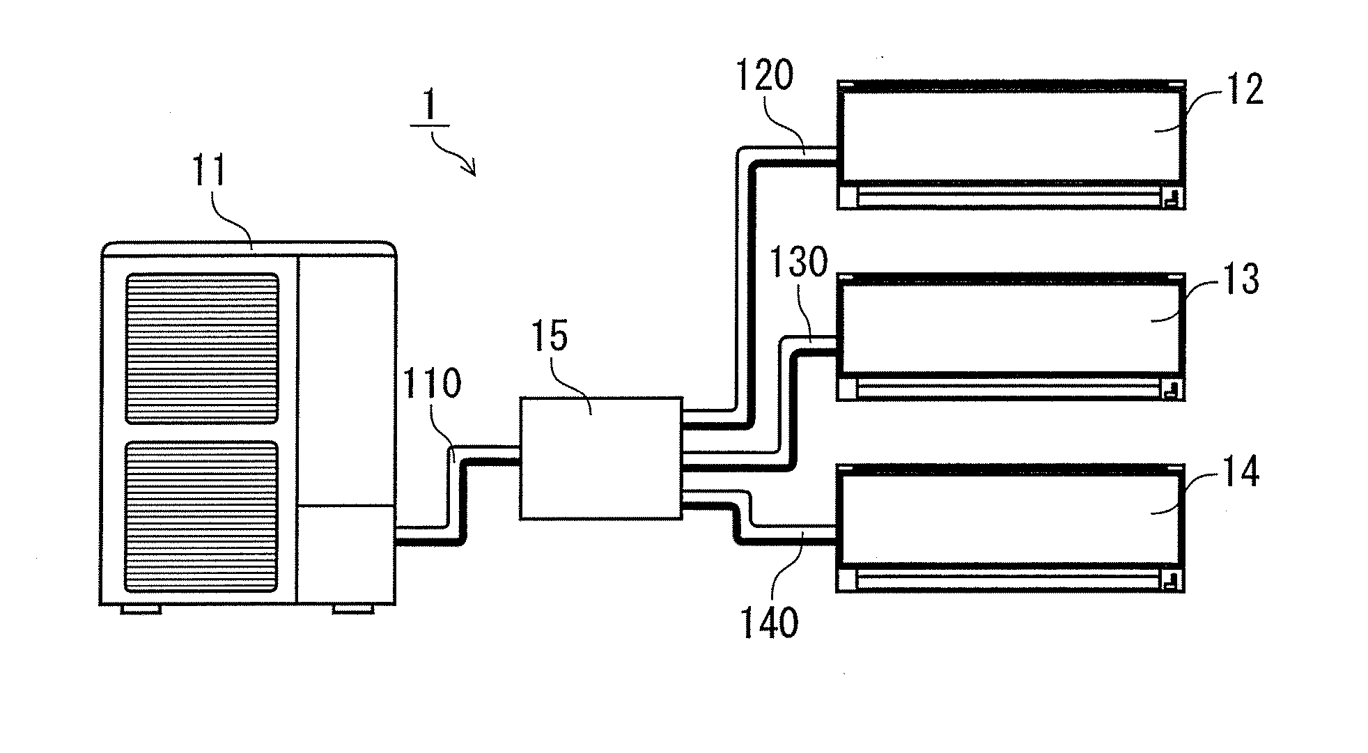
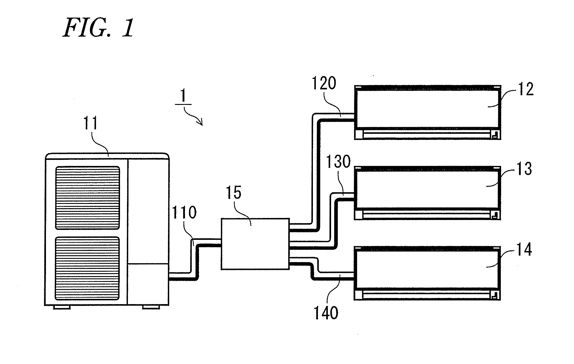
[0021]An air conditioner 1 shown in FIG. 1 includes an outdoor unit 11, and multiple indoor units 12, 13, 14.

[0022]The outdoor unit 11 includes the following composing parts (none of which are shown): that is, a portion of refrigerant circuits respectively for an outdoor heat exchanger, a compressor, a four way valve and the like; a fan for blasting air in order to exchange heat between a refrigerant within the outdoor heat exchanger and the open air; a fan motor for driving the fan; and, a control circuit for controlling the above composing parts.

[0023]The indoor units 12, 13 and 14 respectively include the following composing parts (none of which are shown): that is, a portion of refrigerant circuits respectively for an indoor heat exchanger and the like; a fan for blasting air in order to exchange heat between a refrigerant within the indoor heat exchanger and the open air; a fan motor for driving the fan; and, a control circuit for controlling the above composing parts.

[00...


PUM


Abstract

A refrigerant distribution unit for an air conditioner, includes: a pipe unit which distributes a refrigerant from a refrigerant pipe on an outdoor unit side to multiple branch refrigerant pipes, which includes an electromagnetic valve and a temperature sensor, on an indoor unit side; a main unit which stores the pipe unit covered by an insulator case, upper and lower cases; and an electric component box which controls the electromagnetic valves and the temperature sensors by connecting the valves with the sensors by cables. A cable draw-out recessed portion is formed in one of side faces of the insulator case where the connecting slots for the pipes are formed, and a bottom face recessed portion for storing the cables is formed in a bottom face of the insulator case. The upper case includes a cable draw-out slot for guiding the cables to a cable guide hole formed in the electric component box.

Description

[0001]This application claims priority from Japanese Patent Application No. 2010-148523, filed on Jun. 30, 2010, the entire contents of which are hereby incorporated by reference.FIELD OF THE INVENTION[0002]The present disclosure relates to a refrigerant distribution unit for an air conditioner which is used to distribute a refrigerant from an outdoor unit of the air conditioner to multiple indoor units thereof. Specifically, the present disclosure relates to enhanced safety and enhanced efficiency of an installation operation of the refrigerant distribution unit.DESCRIPTION OF RELATED ART[0003]As a refrigerant distribution unit for distributing a refrigerant from an outdoor unit of an air conditioner to multiple indoor units thereof, for example, as disclosed in Japanese Patent Application Publication No. JP-A-2006-300381, there is known a refrigerant distribution unit which is capable of changing an installation surface of an electric component box according to an installation sit...

Claims


Application Information

Patent Timeline
Patent Type & Authority Applications(United States)
IPC IPC(8): F25B7/00
CPCF24F1/26F25B41/003F24F1/34F24F1/32F25B41/42
Inventor MATSUURA, SHUNYAMASHITA, HARUKI
Owner FUJITSU GENERAL LTD
Why Eureka
Try Eureka