Unit for refrigerant cycle device

a cycle device and refrigerant technology, applied in indirect heat exchangers, lighting and heating apparatus, transportation and packaging, etc., can solve the problems of difficult piping structure (refrigerant passage structure) for distributing refrigerant to the tubes of the first and second evaporators, and achieve the effect of simple passage structure of the unit for the refrigerant cycle devi

Inactive Publication Date: 2007-07-26
DENSO CORP
View PDF13 Cites 22 Cited by
  • Summary
  • Abstract
  • Description
  • Claims
  • Application Information

AI Technical Summary

Benefits of technology

[0009]In the unit, one of the first evaporator and the second evaporator has a tank structure that includes a tank for distributing refrigerant into a plurality of refrigerant passages of the heat exchanging part or for collecting the refrigerant from the refrigerant passages, and the tank has therein a first space into which the refrigerant discharged from the outlet of the ejector flows, and a second space into which the refrigerant to be drawn into the refrigerant suction port flows. In addition, the first space and the second space are partitioned from each other in the tank and are provided such that the refrigerant discharged from the outlet of the ejector flows into the heat exchanging part of the first ev...

Problems solved by technology

However, in this case, piping structure (refrigerant passage structure) for distr...

Method used


Image

  • Unit for refrigerant cycle device
  • Unit for refrigerant cycle device
  • Unit for refrigerant cycle device

Examples


first embodiment

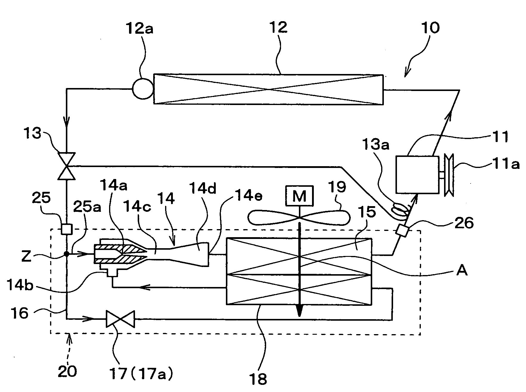
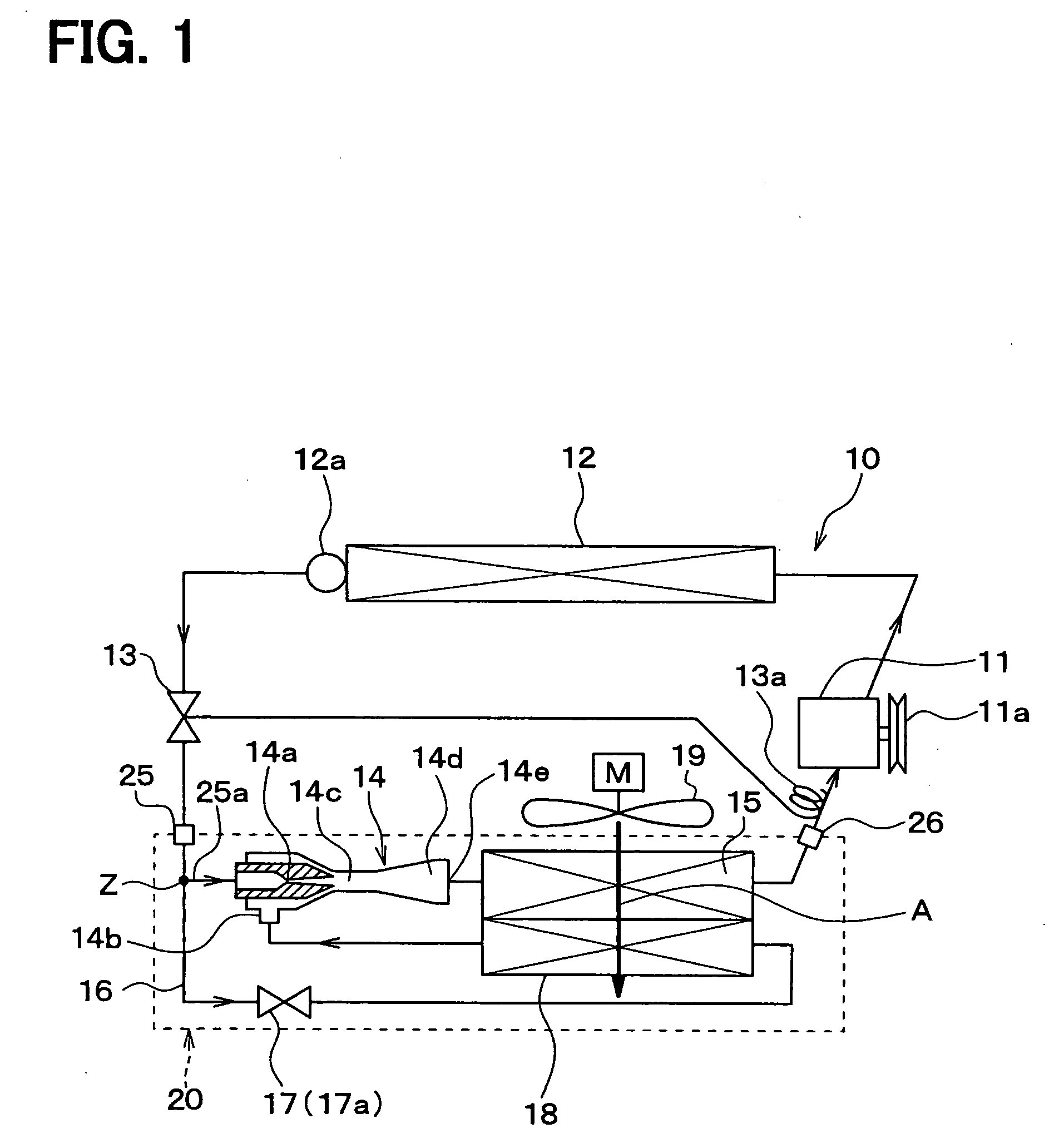
[0040]A first embodiment of the invention and examples of the first embodiment will be described below with reference to FIGS. 1 to 18. In the embodiment, a unit for an ejector refrigerant cycle device and an ejector refrigerant cycle device using the unit will be now described. For example, the unit is an evaporator unit or an ejector-equipped evaporator unit, for a refrigerant cycle.

[0041]This unit is connected to other components of the refrigeration cycle, including a condenser, a compressor, and the like, via piping to constitute a refrigerant cycle device including an ejector. The unit of the embodiment is used for application to an indoor equipment (i.e., evaporator) for cooling air. The unit may be used as an outdoor equipment in other embodiments.

[0042]In an ejector refrigerant cycle device 10 shown in FIG. 1, a compressor 11 for drawing and compressing refrigerant is driven by an engine for vehicle traveling (not shown) via an electromagnetic clutch 11a, a belt, or the lik...

second embodiment

[0177]In the first embodiment, the expansion valve type cycle including the liquid receiver 12a on the outlet side of the radiator 12, and the expansion valve 13 disposed on the outlet side of the liquid receiver 12a is employed. However, in a second embodiment, as shown in FIG. 19, an accumulator 50 is provided which serves as a liquid-vapor separator for separating the refrigerant into liquid and vapor phases on the outlet side of the first evaporator 15, and for storing the excessive refrigerant in the form of liquid. The vapor-phase refrigerant is derived from the accumulator 50 into the suction side of the compressor 11.

[0178]In the accumulator cycle of the FIG. 19, a liquid-vapor interface between the vapor-phase refrigerant and the liquid-phase refrigerant in the accumulator 50 is formed, and hence it is not necessary to control the superheat degree of the refrigerant at the outlet of the first evaporator 15 by the expansion valve 13 like the first embodiment.

[0179]Since the ...

third embodiment

[0181]The third embodiment is a modified one from the second embodiment. As shown in FIG. 20, the accumulator 50 is integrally incorporated into the integrated unit 20 as one element. The outlet part of the accumulator 50 constitutes the refrigerant outlet 26 of the entire integrated unit 20. In the third embodiment, the other parts can be made similarly to the above-described second embodiment.


PUM


Abstract

A unit for a refrigerant cycle device includes an ejector that has a nozzle part which decompresses refrigerant, and a refrigerant suction port from which refrigerant is drawn by a high-speed refrigerant flow jetted from the nozzle part, a first evaporator connected to the outlet of the ejector, and a second evaporator connected to the refrigerant suction port of the ejector. One of the first evaporator and the second evaporator has a tank structure that includes a tank for distributing refrigerant into or for collecting the refrigerant from refrigerant passages of a heat exchanging part. The tank has therein a first space through which the refrigerant discharged from the outlet of the ejector flows into a heat exchanging part of the first evaporator, and a second space through which the refrigerant to be drawn into the refrigerant suction port flows into a heat exchanging part of the second evaporator.

Description

CROSS REFERENCE TO RELATED APPLICATION[0001]This application is based on Japanese Patent Application No. 2006-12461 filed on Jan. 20, 2006, the contents of which are incorporated herein by reference in its entirety.FIELD OF THE INVENTION[0002]The present invention relates to a unit for a refrigerant cycle device (ejector refrigerant cycle device), which has an ejector having a function for decompressing refrigerant and a function for circulating the refrigerant.BACKGROUND OF THE INVENTION[0003]An ejector refrigerant cycle device is known which includes an ejector serving as refrigerant decompression means and refrigeration circulating means. The ejector refrigerant cycle device is useful for, for example, a vehicle air conditioner, or a vehicle refrigeration system for refrigerating and freezing loads on a vehicle, or the like. The refrigeration cycle is also useful for a fixed refrigeration cycle system, such as an air conditioner, a refrigerator, or a freezer.[0004]JP-B2-3265649 d...

Claims


Application Information

Patent Timeline
IPC IPC(8): F25B1/06F25B39/02
CPCB60H2001/3298F25B39/02F25B41/00F25B2341/0011F28F9/262F25B2500/18F28D1/05391F28F9/0204F28F9/0246F25B2341/0012
Inventor ISHIZAKA, NAOHISAAUNG, THUYAOSHITANI, HIROSHITAKANO, YOSHIAKIGOCHO, MIKATAKEUCHI, HIROTSUGUOKAMOTO, YOSHIYUKI
Owner DENSO CORP
Why Eureka
Try Eureka