Microchip fluid control mechanism

a technology of fluid control mechanism and microchip, which is applied in the direction of biomass after-treatment, analysis using chemical indicators, instruments, etc., to achieve the effect of simplifying the passage structur

Inactive Publication Date: 2010-05-06
NEC CORP
View PDF6 Cites 4 Cited by
  • Summary
  • Abstract
  • Description
  • Claims
  • Application Information

AI Technical Summary

Benefits of technology

[0011]According to this invention, the need of a valve mechanism conventionally provided in microchips is eliminated to simplify the passage structure, whereby disposable and inexpensive microchip can be provided.

Problems solved by technology

This Non-Patent Document 1 also describes “However, there are only few practical applications and experiences of this technology, and micro fluid control elements such as micro valves and micro pumps are important subjects to be studied for practical applications”.

Method used


Image

  • Microchip fluid control mechanism
  • Microchip fluid control mechanism
  • Microchip fluid control mechanism

Examples


Embodiment Construction

[0029]Firstly, a first embodiment of this invention will be described in detail.

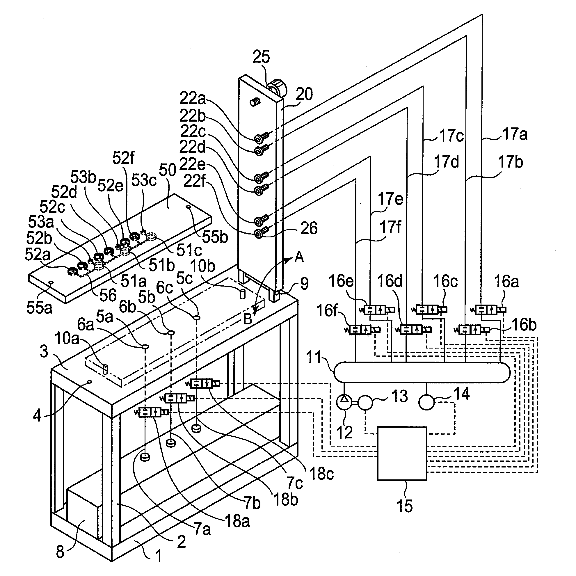
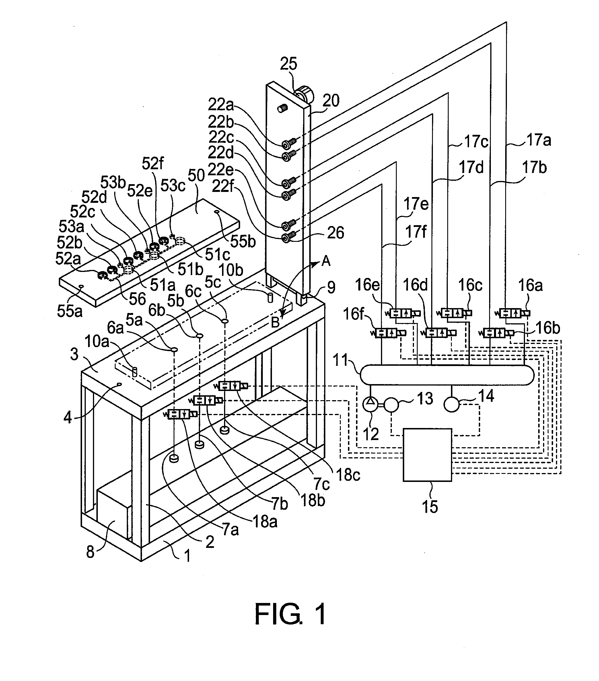
[0030]FIG. 1 is a cross-sectional perspective view showing a configuration of a device for reacting chemical specimens by using a microchip according to the first embodiment of the invention.

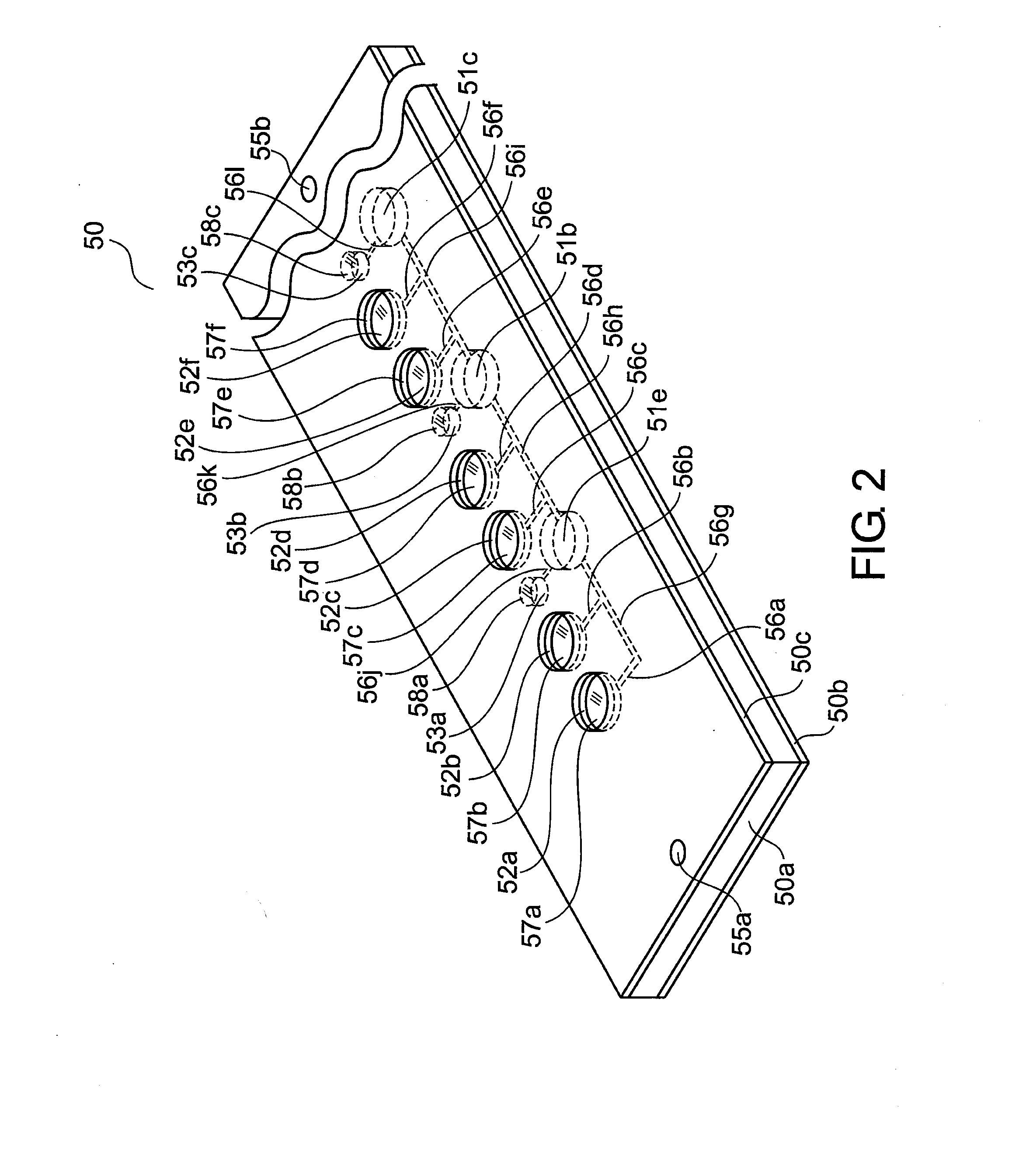
[0031]A table 3 is provided on a machine casing 1 by means of pillars 2, and the table 3 is provided with discharging holes 5a, 5b, 5c the peripheries of which are sealed with O-rings 6a, 6b, 6c, and tubes 7a, 7b, 7c. The discharging holes 5a, 5b, 5c are connected to a waste vessel 8 disposed on the machine casing 1, through discharging electromagnetic valves 18a, 18b, 18c. Pins 10a, 10b are provided so as to project from the upper surface of the table 3, for guiding a microchip 50 to a predetermined position. Further, a cover 20 is provided on the table 3 turnably in directions A and B by means of a hinge 9. The cover 20 has a fastening screw 25 and pressurizing holes 22a, 22b, 22c, 22d, 22e, 22f the peripheries of ...


PUM

PropertyMeasurementUnit
pressureaaaaaaaaaa
stretchableaaaaaaaaaa
volumesaaaaaaaaaa

Abstract

Compressed gas is supplied from above to a specimen vessel having an open top. Transfer channels to reaction vessels are provided under a microchip and transfer channels extending from the reaction vessels are provided on the microchip. Transfer element is provided outside the microchip so as to supply the compressed gas from a member (cover) holding the microchip.

Description

TECHNICAL FIELD[0001]This invention relates to a microchip fluid control mechanism and, in particular, to a micro-analysis chip used for reacting, mixing, separating or analyzing chemical specimens or for analyzing genes, and having a plurality of reaction vessels and specimen vessels, the reaction vessels and the specimen vessels being connected through microchannels.BACKGROUND ART[0002]As described in “Micromachine Technology for Biochemical and Microchemical Analysis Systems” by SHOJI Shuichi (Non-Patent Document 1), and Japanese Laid-Open Patent Publication No. 2002-214241 (Patent Document 2), numerous studies have recently been made on gene analyses performed by reacting samples or liquid specimens on a micro reactor, a micro array, or a single microchip called “Lab-on-a-chip”. Studies also have been made on mechanisms for sequentially transferring extremely small volumes of liquid specimens and on controlling mechanisms.[0003]Non-Patent Document 1 discloses in chapter “2. μTAS...

Claims


Application Information

Patent Timeline
Patent Type & Authority Applications(United States)
IPC IPC(8): G01N35/08G01N37/00G01N33/50B81B7/04
CPCG01N35/08
Inventor ASOGAWA, MINORUHAGIWARA, HISASHIHIRAMATSU, TOHRU
Owner NEC CORP
Why Eureka
Try Eureka