Oil passage structure for internal combustion engine

a technology of internal combustion engine and passage structure, which is applied in the direction of machine/engine, auxillary lubrication, etc., can solve the problems of difficult mounting and difficult production, and achieve the effects of high flexibility in the layout of parts, superior space efficiency and simplified passage structur

Active Publication Date: 2015-09-24
NISSAN MOTOR CO LTD
View PDF6 Cites 0 Cited by
  • Summary
  • Abstract
  • Description
  • Claims
  • Application Information

AI Technical Summary

Benefits of technology

[0007]According to the present invention, the chain system parts, such as chain tensioner, are mounted on the cover for gallery to form the oil gallery between the cover and the wall surface of the engine body. With this, it is possible to directly supply engine oil to the chain system parts from the oil gallery through the oil supply port of the cover. Therefore, an oil passage structure is simplified, and space efficiency is superior, and flexibility in the layout of the parts is high, as compared with a case that the cover and the chain system parts are mounted separately, thereby substantially improving mountability on vehicles.

Problems solved by technology

However, as mentioned above, in case of forming the oil galleries by casting-out at the time of casting or by machining, there is a case that the production is difficult due to a limitation of equipment or a high cost equipment investment being required.
Therefore, there is a problem that the mounting is difficult due to a severe limitation of layout.

Method used


Image

  • Oil passage structure for internal combustion engine
  • Oil passage structure for internal combustion engine
  • Oil passage structure for internal combustion engine

Examples


Embodiment Construction

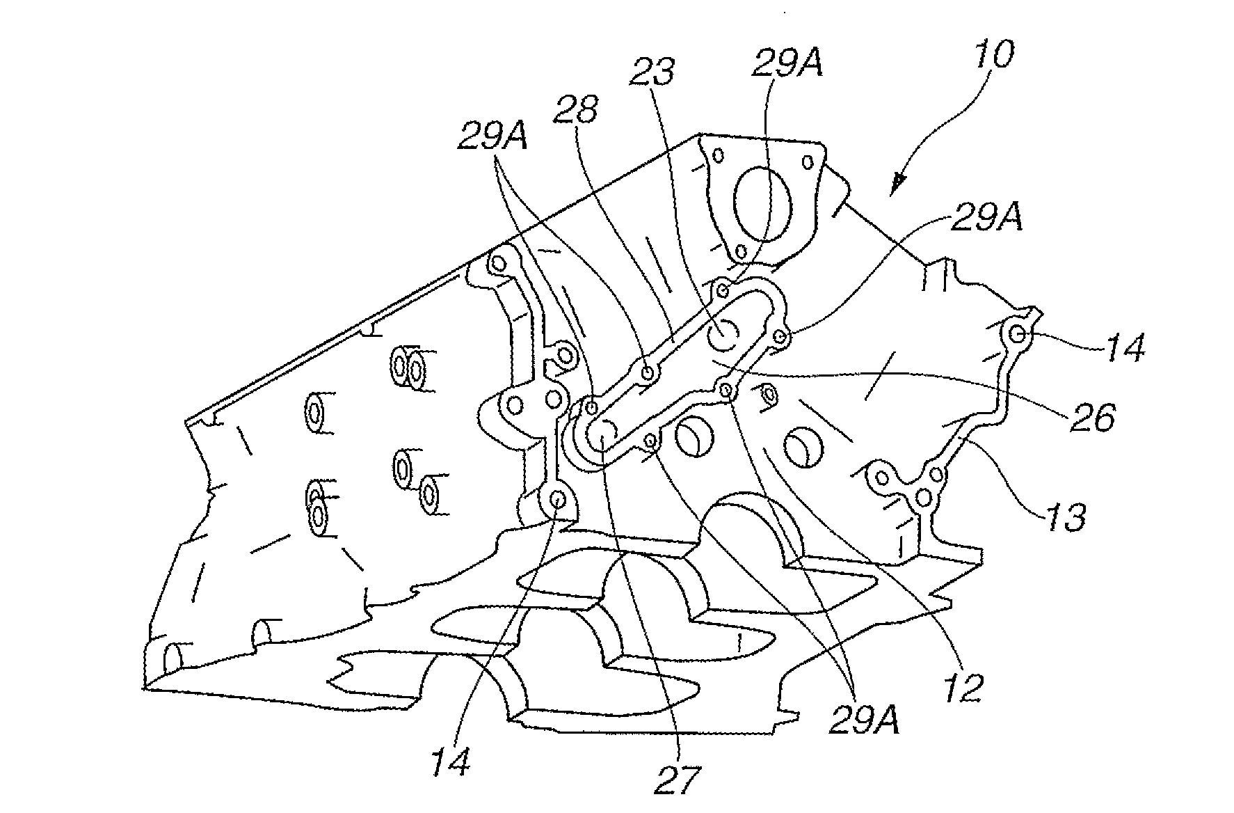
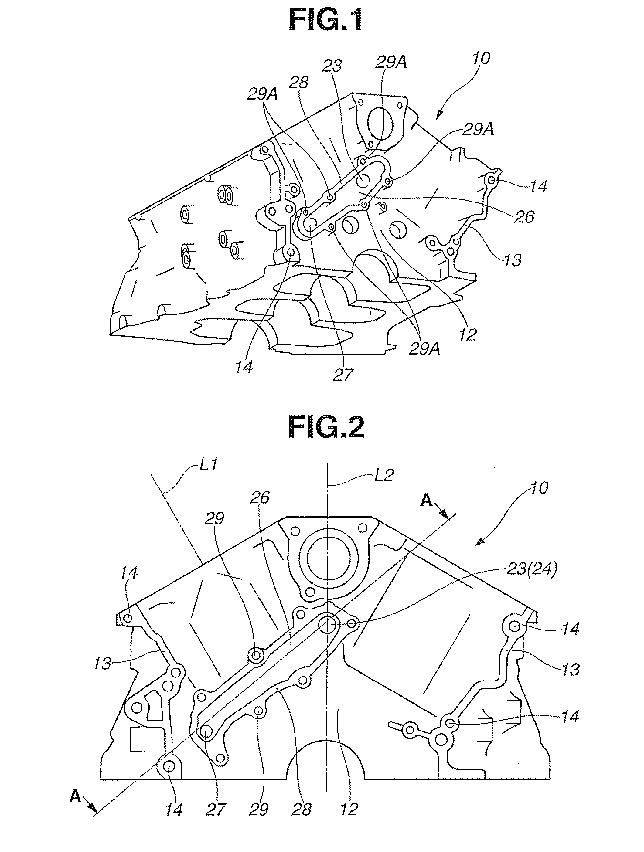
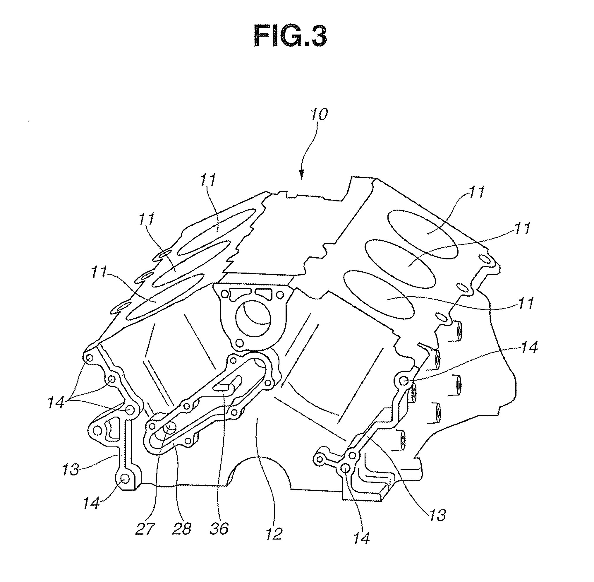
[0023]In the following, the present invention is explained according to the embodiments shown in the drawings. FIG. 1 to FIG. 5 show as a single body cylinder block 10 of the internal combustion engine according to the first embodiment of the present invention. As shown in the same drawings, this cylinder block 10 is used for a V-type six-cylinder internal combustion engine and cast by a metal material such as aluminum alloy or cast iron. Three cylinder bores 11 are arranged in each of right and left banks along the direction of cylinder row (direction of a crankshaft).

[0024]Flange portions 13 to mount thereon a front cover (not shown in the drawings) are mounted on a peripheral edge portion of wall surface 12 on the front side of cylinder block 10. A plurality of bolt holes 14 to insert bolts for a cover to fasten and fix the front cover are formed in these flange portions 13. In addition, an automatic transmission and a torque converter are arranged at the back of cylinder block 1...


PUM


Abstract

Cover (25) is mounted on wall surface (12) on the front side of cylinder block (10). Sub gallery (26) through which engine oil flows is formed between cover (25) and wall surface (12). Chain tensioner (17) is mounted on cover (25), and the engine oil in sub gallery (26) is supplied to chain tensioner (17) through oil supply port (31) formed through cover (25).

Description

TECHNICAL FIELD[0001]The present invention relates to an oil passage structure for an internal combustion engine.BACKGROUND OF THE INVENTION[0002]Oil galleries are formed in an engine body, such as a cylinder block of an internal combustion engine, in order to supply oil to parts requiring oil supply, such as a hydraulic driving apparatus, in addition to bearing parts and sliding parts requiring lubrication (see Patent Publication 1). Such oil galleries are monolithically formed by casting-out at the time of casting of the cylinder block or by machining such as drilling. In addition, end opening portions, which are not used, opening at front and back wall surfaces of the cylinder block are closed by plugs.PRIOR ART REFERENCEPatent Publication[0003]Patent Publication 1: Japanese Patent Application Publication 2004-270478SUMMARY OF THE INVENTIONTask to be Solved by the Invention[0004]However, as mentioned above, in case of forming the oil galleries by casting-out at the time of castin...

Claims


Application Information

Patent Timeline
Patent Type & Authority Applications(United States)
IPC IPC(8): F01M1/12
CPCF01M1/12F01M11/02F02B67/06F16H7/08F16H2007/0812F01M9/108F01M2011/0087F16H2007/0842F01M2011/021F01M9/106
Inventor MOCHIDA, HIROAKITOOYAMA, HIDEAKI
Owner NISSAN MOTOR CO LTD
Why Eureka
Try Eureka